2CKA001473B9185
│
05.12.2018
Product manual
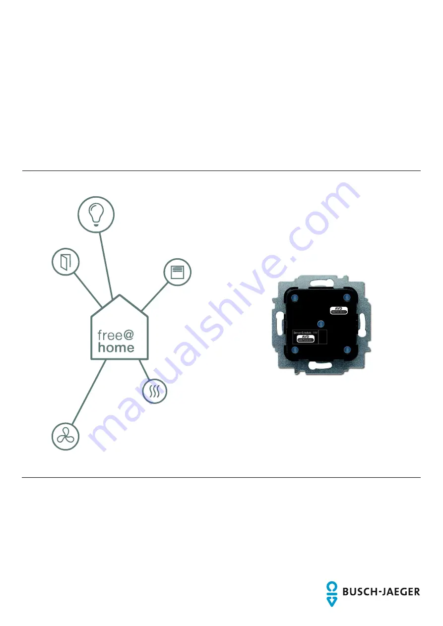
Busch-free@home
®
Sensor/Switch actuator 1/1gang; 2/1gang; 2/2gang, wireless
6211/1.1-WL 6211/2.1-WL
Страница 1: ...2CKA001473B9185 05 12 2018 Product manual Busch free home Sensor Switch actuator 1 1gang 2 1gang 2 2gang wireless 6211 1 1 WL 6211 2 1 WL ...
Страница 2: ...ons 14 5 3 Circuit diagrams 15 5 4 Installation 16 6 Commissioning 18 6 1 Coupling of wireless devices with the System Access Point 19 6 1 1 Resetting the wireless device to the factory settings 19 6 2 Allocation of devices and definition of channels 21 6 2 1 Add device 21 6 3 Setting options per channel 26 6 3 1 Settings Overview of setup menus 27 6 3 1 1 Parameter settings of 1 1gang sensor swit...
Страница 3: ...Table of contents Product manual 2CKA001473B9185 3 10 Notes 35 11 Index 36 ...
Страница 4: ... to property and ensure both reliable operation and a long service life for the device Please keep this manual in a safe place If you pass the device on also pass on this manual along with it Busch Jaeger accepts no liability for any failure to observe the instructions in this manual If you require additional information or have questions about the device please contact Busch Jaeger or visit our I...
Страница 5: ... respective warning symbol in connection with the signal word Danger indicates an imminently threatening danger which leads to death or serious irreversible injuries Warning Serious damage to health The respective warning symbol in connection with the signal word Warning indicates a threatening danger which can lead to death or serious irreversible injuries Caution Damage to health The respective ...
Страница 6: ...ociated risk is borne exclusively by the user operator The device is not intended for the following Unauthorized structural changes Repairs Outdoor use The use in bathroom areas 2 4 Target group Qualifications of personnel Installation commissioning and maintenance of the device must only be carried out by trained and properly qualified electrical installers The electrical installer must have read...
Страница 7: ...s Caution R is k of damaging the device due to external factors Moisture and contamination can damage the device Protect the device against humidity dirt and damage during transport storage and operation 2 6 Environment Cons ider the protection of the environment Used electric and electronic devices must not be disposed of with domestic waste The device contains valuable raw materials which can be...
Страница 8: ...zed flush mounted installation The devices serve both as control element as well as actuator for the activation of electric loads Sensor and actuator are combined in a flush mounted insert 1 The sensor and switching channels have been pre programmed at the point of delivery button top bottom off on left rocker However this pre configuration can be adjusted as required After connecting the load it ...
Страница 9: ... channels Actuator channels S witching load 6211 1 1 WL Sensor switch actuator 1 1gang wireless 1 1 1 x 2300 W 6211 2 1 WL Sensor switch actuator 2 1gang wireless 2 1 1 x 2300 W 6211 2 2 WL Sensor switch actuator 2 2gang wireless 2 2 1 x 2300 W Table 1 Overview of types 3 3 Functions The following table provides an overview of the possible functions and applications of the device Icon of the opera...
Страница 10: ...185 10 3 4 Device overview 1 3 4 2 Fig 2 Device overview of sensor switch actuator Phase sensing L 6 Mark TOP 7 Multi point connector 8 Terminal block Fig 3 Sensors 1 Sensor for sensor switch actuator 1 1gang 2 Sensor for sensor switch actuator 2 1gang and 2 2gang ...
Страница 11: ... Transmission frequency 2 400 2 483 GHz Maximum transmission power WL wireless 15 dBm Power consumption 1 W Maximum load 1gang switch actuator 1 x 10 Ax 2gang switch actuator 2 x 5 A 4 Ax Protection type IP20 Ambient temperature 5 C 45 C Storage temperature 20 C 70 C Table 3 Technical data 4 1 Types of load S ens or s witch actuator 1 1gang S ens or s witch actuator 2 1gang S ens or s witch actuat...
Страница 12: ...ct manual 2CKA001473B9185 12 4 2 Dimensional drawings NOTE All dimensions are specified in mm All device types listed in this manual have the same dimensions 71 51 51 71 32 45 Fig 4 Dimensions of all described device types all dimensions in mm ...
Страница 13: ...ch free home This can be downloaded via www busch jaeger de freeathome Note Transmitter and receiver communicate via radio control The transmission range depends on the structural conditions Walls and ceilings especially steel reinforcements or metal claddings reduce the transmission range The distance of components to other transmitters that also emit high frequency signals e g computers audio an...
Страница 14: ...you have the necessary electrical engineering knowledge and experience Incorrect installation endangers your life and that of the users of the electrical system Incorrect installation can cause serious damage to property e g due to fire The minimum necessary expert knowledge and requirements for the installation are as follows Apply the five safety rules DIN VDE 0105 EN 50110 1 Disconnect 2 Secure...
Страница 15: ...nd installation Circuit diagrams Product manual 2CKA001473B9185 15 5 3 Circuit diagrams A B L N 10 A L N 1 L N 10 A L N 1 L N L N 1 2 10 A A B C Fig 5 Electrical connection Ⓐ 6211 1 1 WL Ⓑ 6211 2 1 WL Ⓒ 6211 2 2 WL ...
Страница 16: ...steps Note The sensor must be pulled off the flush mounted insert before mounting Note Observe correct wiring 1 Turn the device into the correct installation position 1 2 Connect the 230 V power cord to the bottom terminal block 2 Obs erve Chapter 5 3 Circuit diagrams on page 15 3 Insert the device into the flush mounted box and screw it on Abb 6 Connection and installation 4 Attach the cover rock...
Страница 17: ...and installation Installation Product manual 2CKA001473B9185 17 6 Attach the cover with mounted sensor to the flush mounted insert Observe the correct position of the sensor connection 1 Fig 9 Mounting the sensor ...
Страница 18: ...g When energized a device that has not been programmed is in programming mode for 30 minutes and can be logged into the system Programmed devices share information about their type and supported functions with the System Access Point During initial commissioning all devices are given a universal name e g sensor switch actuator sensor dimming actuator sensor blind actuator room temperature controll...
Страница 19: ...er supply of the free home wireless devices The devices are now in programming mode for 30 minutes Fig 10 Coupling wireless devices with the System Access Point 4 In the user interface of the System Access Point select System settings free home Wireless settings Search for wireless devices The System Access Point consecutively scans all free home wireless devices Devices that are in programming mo...
Страница 20: ... button at the bottom left pressed 3 Re energize the device The LED flashes slowly for 10 seconds then fast for 5 seconds and then goes out The factory settings are restored and the device can now be programmed again Note Devices which are already in factory settings are not reset again The LED remains out in step 3 ...
Страница 21: ...ractical name The allocation is made via the allocation function of the Web based user interface of the System Access Point 6 2 1 Add device 1 In the Add devices bar select the desired application and pull it via drag and drop into the floor plan Fig 11 Dragging the application from the add bar A pop up window opens which lists all the devices that are connected to the bus and suitable for the sel...
Страница 22: ...n of channels Product manual 2CKA001473B9185 22 Fig 12 Pop up window with the suitable devices Identification The device can be identified via the serial number or via switching Identification via s erial number Fig 13 Identification via serial number ...
Страница 23: ...ls Product manual 2CKA001473B9185 23 Compare the serial number and the short ID of the identification label which is glued on the device with the numbers and IDs in the list This is how the searched for device and possibly the searched for channel are identified ...
Страница 24: ...dentification via s witching only s uitable for actuators Fig 14 Identification via switching 1 Select a device and a channel from the list 2 Press the button in the detailed view of the device The connected load is switched 3 Repeat the last two steps until you have located the searched for device ...
Страница 25: ...r Living room blind 2 Press the tick at the bottom right This takes over the entry NOTE The settings of the device can be adjusted via the Web based user interface of the System Access Point For pre programmed devices the default settings can be adjusted This allows the channel selection to be influenced For these settings however a fitter access is partly necessary see online Help of the System A...
Страница 26: ... settings are made via the allocation function of the Web based user interface of the System Access Point S elect device Fig 16 Select device 1 Select the device icon 1 in the floor plan of the working area view All setting options for the respective channel are displayed in the list view 2 For rockers sensors the corresponding rocker must be selected The following settings are available ...
Страница 27: ... switch off delay in seconds The buttons can be used to specify for example how long the light remains switched on after the sensor has deactivated the load 6 Behaviour during faults Display of information only No settings are possible Fig 17 Actuator settings Note The function of the actuator can be specified after the allocation Switch actuator heating operation additional heating stage or trigg...
Страница 28: ...3 Setting the LED night day switch on brightness in via the buttons The parameter specifies how strong the LED lights up percentage wise during night day 4 Selecting the LED operating mode Light for orientation LED lights up permanently Status display LED lights up during actuation Fig 19 Rocker settings The following parameter is available immediately for pre programmed devices ...
Страница 29: ...g the function Control element Dimming sensor Staircase light sensor Force position sensor On Off Blind sensor Blind force position Scene sensor is visible only when the Scene sensor has been selected Long press of the button Overwrite scene Retain scene Fig 20 Rocker setting after linking with actuator NOTE The parameter only functions when a time profile with the application LED day night switch...
Страница 30: ...ist view R ocker s ettings As for 1 1gang However the settings are made for two rockers left rocker and right rocker 6 3 1 3 Parameter s ettings of 2 2gang s ensor s witch actuator Actuator s ettings As for 1 1gang However two actuator channels are available S ens or s ettings As for 1 1gang However two rockers left and right rocker are displayed in the list view R ocker s ettings As for 1 1gang H...
Страница 31: ...ensor since they are combined in the one device 6 4 1 Linking actuator and sensor Fig 21 Linking actuator and sensor 1 On the working area select the sensor 1 that is to be linked with the actuator 2 Select the actuator 2 that is to be served by the sensor 3 Press the tick at the bottom right to take over the entries A blue connecting line indicates the link between the two devices The configurati...
Страница 32: ...second sensor 1 that is to be linked with the actuator 2 Select the actuator 2 that is to be served by the sensor 3 Press the arrow at the bottom right to take over the entries An additional blue connecting line indicates the link between the two devices After the transmission of the configuration the sensor can be operated directly locally ...
Страница 33: ...ailable in the electronic catalogue www busch jaeger catalogue com 9 Maintenance The device is maintenance free In case of damage e g during transport or storage do not perform repairs Once the device is opened the warranty is void Access to the device must be guaranteed for operation testing inspection maintenance and repairs according to DIN VDE 0100 520 9 1 Cleaning Caution R is k of damaging t...
Страница 34: ...e measured via the phase sensor L and determined whether the device carries current after being connected If it carries current the cause of the fault is not the electronic insert Fig 23 Phase sensing L 1 Pull off the rocker and the sensor 2 2 Feed the probe of the ammeter into the phase sensor L 1 The measuring device indicates whether the device carries current ...
Страница 35: ...Notes Diagnosis of faults Product manual 2CKA001473B9185 35 10 Notes ...
Страница 36: ... LED 8 Liability 4 Links 31 actuator 31 Additional sensors 31 sensor 31 M Maintenance 33 N Notes 35 O Operation 33 Overview of types 9 P Parameter settings Sensor switch actuator 1 1gang 27 Sensor switch actuator 2 1gang 30 Sensor switch actuator 2 2gang 30 Planning instructions 13 Protection type 11 Q Qualification of personnel 6 S Safety 5 Safety instructions 7 14 Scope of supply 9 Select device...
Страница 37: ... the contents of this document without prior notice The detailed specifications agreed upon apply for orders ABB accepts no responsibility for possible errors or incompleteness in this document We reserve all rights to this document and the topics and illustrations contained therein The document and its contents or extracts thereof must not be reproduced transmitted or reused by third parties with...