Product manual
│
15.11.2021
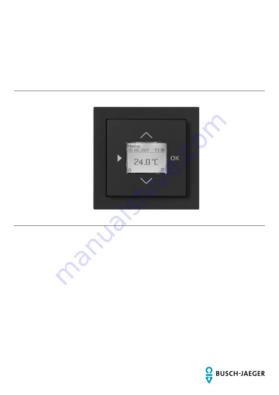
Electronic room temperature controller insert
1098 U-102 1098 UF-102
Branding -- Release 2018-01-01
Страница 1: ...Product manual 15 11 2021 Electronic room temperature controller insert 1098 U 102 1098 UF 102 Branding Release 2018 01 01 ...
Страница 2: ...a 12 5 2 Dimensional drawings 13 6 Connection installation mounting 14 6 1 Requirements for the electrician 14 6 2 Mounting dismantling 15 6 3 Electrical connection 18 7 Commissioning 19 7 1 Initial commissioning 19 7 2 Factory settings 21 8 Operation 23 8 1 Button assignment 23 8 2 Operating modes 24 8 2 1 Operating mode selection 24 8 2 2 AUTO 25 8 2 3 OFF 26 8 2 4 Comfort ECO 27 8 2 4 1 Comfort...
Страница 3: ... 4 1 Navigation to the expert settings 32 8 4 2 Expert settings Options 33 8 4 3 Expert settings Special functions 34 8 4 4 Expert settings Factory settings 35 8 5 Error messages 36 8 5 1 Floor sensor is not connected 36 9 Maintenance 37 9 1 Cleaning 37 10 Notes 38 11 Index 39 ...
Страница 4: ...e to property and ensure both reliable operation and a long service life for the device Please keep this manual in a safe place If you pass the device on also pass on this manual along with it Busch Jaeger accepts no liability for any failure to observe the instructions in this manual If you require additional information or have questions about the device please contact Busch Jaeger or visit our ...
Страница 5: ... the signal word Danger indicates an imminently threatening danger which leads to death or serious irreversible injuries Warning Serious damage to health The respective warning symbol in connection with the signal word Warning indicates a threatening danger which can lead to death or serious irreversible injuries Caution Damage to health The respective warning symbol in connection with the signal ...
Страница 6: ...th the connecting options available on the device Use for electric as well as water borne heating systems The intended use also includes adherence to all specifications in this manual 2 3 Improper use Each use not listed in Chapter 2 2 Intended use on page 6 is deemed improper use and can lead to personal injury and damage to property Busch Jaeger is not liable for damages caused by use deemed con...
Страница 7: ...The electrical installer must have read and understood the manual and follow the instructions provided The electrical installer must adhere to the valid national regulations in his her country governing the installation functional test repair and maintenance of electrical products The electrical installer must be familiar with and correctly apply the five safety rules DIN VDE 0105 EN 50110 1 Disco...
Страница 8: ... qualified electricians Disconnect the mains power supply before installation disassembly Never use the device with damaged connecting cables Do not open covers firmly bolted to the housing of the device Use the device only in a technically faultless state Do not make changes to or perform repairs on the device on its components or its accessories Keep the device away from water and wet surroundin...
Страница 9: ...evice at the appropriate collecting depot All packaging materials and devices bear the markings and test seals for proper disposal Always dispose of the packaging material and electric devices and their components via the authorized collecting depots and disposal companies The products meet the legal requirements in particular the laws governing electric and electronic devices and the REACH ordina...
Страница 10: ...Setup and function Product manual 2CKA001473B5267 10 4 Setup and function 4 1 Device overview 4 2 1 2 3 Fig 1 Overview of devices 1 Type plate 2 Connecting plug 3 Electric connecting terminals 4 Display ...
Страница 11: ...temperature regulation via switch contact The timing of the temperature regulation can be set for each day The temperature values can be set for individual days or in a block The device can be used with electric as well as water based heating systems Notice The device is not suited for proportional control ...
Страница 12: ...e 1 5 mm 4 0 mm 6 7 mm 0 8 Nm Switching capacity 250 V AC 16 2 A Power consumption standby 0 05 W Protection class II Operating temperature 0 C 35 C Storage temperature 20 C 70 C Degree of protection via housing IP21 Quartz accuracy at 20 C 0 5 sec day Operating mode DIN EN 60730 1 1 BSTU Pollution degree DIN EN 60730 1 2 Surge voltage DIN EN 60730 1 4000 V Floor sensor NTC 10 kΩ at 25 C External ...
Страница 13: ...Technical data Product manual 2CKA001473B5267 13 5 2 Dimensional drawings 20 17 8 Fig 2 Dimensions Notice All specifications are in mm ...
Страница 14: ...our life and that of the user of the electrical system Incorrect installation can cause serious damage to property e g due to fire The minimum necessary expert knowledge and requirements for the installation are as follows Apply the five safety rules DIN VDE 0105 EN 50110 1 Disconnect 2 Secure against being re connected 3 Ensure there is no voltage 4 Connect to earth and short circuit 5 Cover or b...
Страница 15: ...he flush mounted insert must only be installed in flush mounted boxes according to DIN 49073 1 Part 1 or suitable surface mounted housings Different installation standards apply in other countries These are to be taken into account when used in connection with a different support ring and flush mounted box To mount the device proceed as follows 1 Pull the attachment off If the device is already mo...
Страница 16: ...first the resistance of the plastic clamps must be overcome Fig 4 Device in as delivered state pulling off the attachment 3 Connect the cables to the flush mounted insert For the connection assignment see chapter Chapter 6 3 Electrical connection on page 18 Fig 5 Connecting the cables ...
Страница 17: ...nted insert 5 Mount the attachment together with the cover frame onto the flush mounted insert Ensure that the connector is not jammed on the rear side If mounting is difficult check whether a burr has formed at the lock in openings of the flush mounted insert and remove it The device is now mounted Fig 7 Mounting the attachment ...
Страница 18: ...rical connection L N 1 A 6 L L EXT N Sensor PE L T Fig 8 Electrical connection with remote sensor 1098 UF 102 L N 1 A 6 L L EXT N Sensor PE L T Fig 9 Electrical connection without remote sensor 1098 U 102 6 7 mm Fig 10 Skinning length Notice The skinning length should be 6 7 mm ...
Страница 19: ...lowing situation First electrical connection Electrical connection see chapter 6 3 Electrical connection on page 18 First mounting of the control element Mounting of the control element see chapter 6 2 Mounting dismantling on page 15 After a reset Reset see chapter 8 4 4 Expert settings Factory settings on page 35 All inputs can also be made later in the settings ...
Страница 20: ...267 20 If no floor sensor is connected the error messages Floor control and Room temperature control floor temperature control are displayed during the selection In this case select the Room control and confirm it Fig 11 Initial commissioning ...
Страница 21: ... manufacturer should be observed Switching times Comfort Mon Fri 7 a m Sat Sun 8 a m ECO Mon Fri 10 p m Sat Sun 10 p m Temperature settings Comfort 23 0 C ECO 19 0 C First switching times when programming changes to 4 events block function Comfort Mon Fri 7 a m 4 p m Sat Sun 8 a m ECO Mon Fri 9 a m 10 p m Sat Sun 10 p m This switching time is not active but can be activated Expert settings Options...
Страница 22: ...tion Floor control At activated combi mode 33 0 C for maximum value of floor sensor 10 0 C for minimum value of floor sensor Frost protection Yes Min max values Max room 30 0 C Min room 5 0 C Max floor 50 0 C Min floor 5 0 C Switching load electric 1000 W Display internal temperature No Offset 0 0 C Valve protection No ...
Страница 23: ...en the step width is increased to 5 2 OK With the OK button the value of a flashing display is confirmed and next parameter is displayed Programming must then be confirmed At a pressure in standard mode 0 6 seconds The selection of standard modes AUTO OFF ECO and Comfort opens and the mode can be adjusted Selection with buttons Λ V and confirmation with OK At a pressure of 0 6 seconds in standard ...
Страница 24: ...1473B5267 24 8 2 Operating modes 8 2 1 Operating mode selection Fig 13 Changing operating mode Activate the selected operating mode by pressing OK The unit automatically returns to the main menu The selected operating mode is active ...
Страница 25: ...9 To set the temperature values see chapter 8 3 4 Comfort ECO Set temperature on page 31 To set 2 or 4 events per day see chapter 8 4 2 Expert settings Options on page 33 This setting is located in the Expert settings menu If you are not sure consult an expert to make the settings The set value can be adjusted with the Up Down buttons and remains valid until the next programmed switching time is r...
Страница 26: ... 16 Operating mode OFF The controller is deactivated With or without frost protection active To set the frost protection when the controller is switched off see chapter 8 4 3 Expert settings Special functions on page 34 This setting is located in the Expert settings area Consult an expert if you need assistance to make the settings ...
Страница 27: ...ed If the time programs are to be active again the AUTO operating mode is selected again To set the temperature values for comfort mode see chapter 8 3 4 Comfort ECO Set temperature on page 31 To set the temperature values for ECO mode see chapter 8 3 4 Comfort ECO Set temperature on page 31 The setpoint can be set with the Up Down buttons If the set value is adjusted manually Manual is shown in t...
Страница 28: ...manually adjusted value remains valid until the next programmed switching time is reached If the set value is adjusted manually the hand icon for Manual is shown in the display 8 3 2 Display switching times Fig 20 Display switching times A short press of the OK button displays the set switching time In the example screen the device changes to Comfort temperature at 6 a m and to ECO mode at 9 p m B...
Страница 29: ...o at least half an hour 2 or 4 switching times events can be set per day To set 2 or 4 events per day see chapter 8 4 2 Expert settings Options on page 33 This setting is located in the Expert settings Consult an expert if you need assistance to make the settings Block Mon Fri Sat Sun or daily programming can be set To set block or daily see chapter 8 4 2 Expert settings Options on page 33 This se...
Страница 30: ...aily and 4 events per day Deactivate start time Start times can also deactivated By doing so you can implement the following circuits With 4 start times on a specific day switching takes place only twice With 2 start times one day is skipped For example on this day the ECO temperature is set Fig 23 Deactivating start time ...
Страница 31: ...3 4 Comfort ECO Set temperature Fig 24 Comfort ECO Setting temperature 8 3 5 Set date time and year Fig 25 Setting date time and year 8 3 6 Operating mode selection To change the operating mode see Chapter 8 2 1 Operating mode selection on page 24 ...
Страница 32: ...Operation Product manual 2CKA001473B5267 32 8 4 Expert settings 8 4 1 Navigation to the expert settings Menu selection of Expert settings Fig 26 Navigation to the expert settings ...
Страница 33: ...n in one of the operating modes AUTO Comfort ECO or OFF must have a minimum duration of 5 seconds The display shows a count down from 5 to 0 seconds If no button is pressed for one minute the button lock is active again 5 8 Display illumination The display illumination can be set on AUTO or ON AUTO If no button is pressed for one minute the display illumination switches off ON The display illumina...
Страница 34: ...re limit for the floor The maximum limit is set to protect wooden floors from being destroyed due to excess temperatures If the internal sensor requests more heat the thermostat won t switch on The minimum temperature keeps the floor warm when there are other heat sources in the room e g a fire place Even if the internal sensors measure a sufficiently warm room the thermostat will control the floo...
Страница 35: ...justed accordingly Adjustable in steps of 0 1 C The Offset also affects the displayed internal temperature value 8 8 Valve protection YES NO If valve protection is activated the load will be switched on every day at 10 00 for at least 5 minutes This function is important if the standard mode is set to OFF 8 4 4 Expert settings Factory settings If the selection Factory settings in the Expert menu i...
Страница 36: ...must be connected If there is no floor sensor connected and one of the applications is activated the message Sensor floor error will be displayed instead of the main menu The buttons have no function The controller carries out a PWM heating control with a 30 ON period To reset the error message switch to the expert settings and select the application Room control see chapter 8 4 3 Expert settings ...
Страница 37: ...ts these can enter the device through crevices Do not spray cleaning agents directly onto the device Aggressive cleaning agents can damage the surface of the device Never use caustic agents abrasive agents or solvents Clean dirty devices with a soft dry cloth If this is insufficient the cloth can be moistened slightly with a soap solution ...
Страница 38: ...Notes Product manual 2CKA001473B5267 38 10 Notes ...
Страница 39: ...Functions 11 I Improper use 6 Information and symbols used 5 Information on protection of the environment 9 Initial commissioning 19 35 Intended use 6 M Maintenance 37 Mounting 15 19 N Notes 38 Notes on the instruction manual 4 O OFF 26 Operating mode selection 24 31 Operating modes 24 Operation 7 23 Options Expert settings 25 29 33 Q Qualification of personnel 7 R Requirements for the electrician...
Страница 40: ... of the ABB Group Freisenbergstraße 2 58513 Lüdenscheid www BUSCH JAEGER de info bje de abb com Central sales service Tel 49 2351 956 1600 Fax 49 2351 956 1700 Copyright 2021 Busch Jaeger Elektro GmbH All rights reserved 2CKA001473B5267 ...