burster Italia s.r.l. · Sede legale ed operativa · Via Cesare Battisti, 16/18 · 24035 Curno (BG) · Tel. +39 035 618120 · Fax +39 035 618250
e-mail: [email protected] · http://www.burster.it
C.F. e P.IVA 11048400151 · Capitale sociale Euro 49.920,00 · R.E.A. di Bergamo 276749
Apparecchi di misura di precisione. Sensori e Sistemi
per grandezze elettriche, termiche e meccaniche
4.4
Couplings
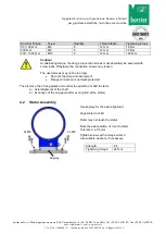
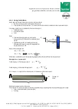
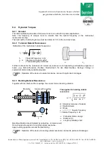
Couplings must be able to balance an axial, radial or angular offset of the shafts and not allow large
forces to act on the sensor.
Axial offset Radial offset Angular offset
If shear forces and axial forces act on the torque sensors, they can cause zero point shifts, which falsify
the measuring signal as a disturbance variable during the measurement.
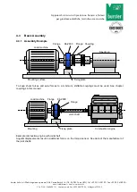
4.4.1 Alignment of the Measurement Arrangement
Precisely alignment of the couplings reduces the reaction forces and increases the durability of the
couplings and the shaft bearing.
Frequently, an alignment of the couplings with a straight edge in two levels, vertical to each other, is
sufficient.
At high speed, however, an alignment of the coupling (shaft ends) with a dial indicator or a laser is
recommended.
Further points to be considered
The axis height of the torque sensor (data sheet) must be considered.
An air gap between rotor and stator must be available. The rotor may not touch the stator in any
operating condition.
Axial position of the rotor to the stator: see data sheet.
For further references see coupling manual and limit thrust load and shear load of the torque
sensor (data sheet).
5
Electrical Connection
5.1
Pin Connection
See test certificate, as well.
12-
pin
Analog Output
View: socket on soldering side
Pin A NC
Pin B NC
Pin C Signal
±5 V / (±10 V)
Pin D Signal GND
0 V
Pin E Excitation GND
0 V
Pin F Exci
12 ... 28 VDC
Pin G Option Speed
TTL
Pin H NC
Pin J NC
Pin K NC
Pin L NC
Pin M Housing
ΔK
a
Δ
K
w
2
x
Δ
K
w
Δ
K
r

