background image

114

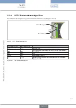
Inbetriebnahme

inBeTrieBnahMe

14. 

sicherheitshinweise

14.1. 

Warnung!

verletzungsgefahr bei unsachgemäßem Betrieb!

Nicht sachgemäßer Betrieb kann zu Verletzungen, sowie Schäden am Gerät und seiner Umgebung führen. 

Vor der Inbetriebnahme muss gewährleistet sein, dass der Inhalt der Bedienungsanleitung dem Bedienungs-

• 

personal bekannt ist und vollständig verstanden wurde.

Die Sicherheitshinweise und die bestimmungsgemäße Verwendung müssen beachtet werden.

• 

Nur ausreichend geschultes Personal darf die Anlage/das Gerät in Betrieb nehmen.

• 

festlegen der grundeinstellungen

14.2. 

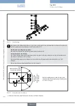
Die Grundeinstellungen des Positioners werden werkseitig durchgeführt.

Zur Anpassung des Positioners an örtliche Bedingungen muss nach der Installation die Funktion 

X.TUNE


ausgeführt werden

ausführen der automatischen anpassung 

14.2.1. 

X.TUNE

:

Warnung!

Während der ausführung der 

X.TUNE

 - funktion bewegt sich das ventil selbsttätig aus seiner augen-

blicklichen stellung!

Führen Sie 

• 

X.TUNE

 niemals bei laufendem Prozess durch!

Verhindern Sie durch geeignete Maßnahmen, dass die Anlage unbeabsichtigt betätigt werden kann!

• 

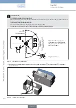
hinWEiS! 

vermeiden sie eine fehlanpassung des reglers durch einen falschen versorgungssdruck oder aufge-
schalteten Betriebsmediumsdruck!

Führen Sie 

• 

X.TUNE


in jedem Fall

 bei dem im späteren Betrieb zur Verfügung stehenden Versorgungsdruck 

(= pneumatische Hilfsenergie) durch.

Führen Sie die Funktion 

• 

X.TUNE

  vorzugsweise 

ohne

 Betriebsmediumsdruck durch, um Störeinflüsse infolge 

von Strömungskräften auszuschließen. 

Zur Durchführung der 

X.TUNE

 muss sich der Positioner im Betriebszustand AUTOMATIK befinden  

(DIP-Schalter 4 = OFF).

Typ 8791

deutsch

Содержание 8791

Страница 1: ...Operating Instructions Bedienungsanleitung Manuel d utilisation Typ 8791 Positioner Electropneumatic positioner Elektropneumatischer Stellungsregler Positionneur électropneumatique ...

Страница 2: ...the right to make technical changes without notice Technische Änderungen vorbehalten Sous réserve de modifications techniques 2009 Bürkert Werke GmbH Co KG Operating Instructions 0911 01_EU ml_00805664 Original DE ...

Страница 3: ...General Description 12 5 1 1 Features 12 5 1 2 Combination with valve types and mounting versions 13 5 1 3 Overview of the mounting options 14 6 Structure 15 6 1 Representation 15 7 Function 16 7 1 Function diagram 16 7 2 Function of the position control 17 7 3 Schematic representation of the position control 18 7 4 Properties of the position controller software 19 7 4 1 Functions I 19 7 4 2 Funct...

Страница 4: ... 27 9 2 Operating status 27 9 3 Control and display elements of the positioner 27 9 3 1 Configuration of the keys 28 9 3 2 Function of the DIP switches 29 9 3 3 Display of the LEDs 30 9 4 Error messages 31 9 4 1 Error messages in MANUAL and AUTOMATIC operating status 31 9 4 2 Error messages while the X TUNE function is running 31 10 Functions 32 10 1 Basic functions 32 10 1 1 DIR CMD Effective sen...

Страница 5: ...or 50 13 2 2 Pin assignment for input signals from the control centre e g PLC M12 8 pole plug 51 13 2 3 Pin assignment for output signals to the control centre e g PLC M 12 8 pole plug required for analogue output option only 51 13 2 4 Pin assignment for operating voltage M12 8 pole circular plug in connector 51 13 3 Electrical Connection with Cable Gland 52 13 3 1 Designation of the screw type te...

Страница 6: ...nection AS Interface 58 15 5 1 Safety Instructions 58 15 5 2 Connection with M12 circular plug in connector 4 pole male 58 16 Service 59 17 Accessories 60 17 1 Communications software PC software based on FDT DTM technology 60 17 1 1 PACTware 3 6 60 17 2 Serial interface RS 232 60 17 3 Download 61 18 Packaging and Transport 62 19 Storage 62 20 Disposal 62 english Type 8791 ...

Страница 7: ...Symbols 1 1 Danger Warns of an immediate danger Failure to observe the warning may result in a fatal or serious injury Warning Warns of a potentially dangerous situation Failure to observe the warning may result in serious injuries or death Caution Warns of a possible danger Failure to observe this warning may result in a medium or minor injury Note Warns of damage to property Failure to observe t...

Страница 8: ... devices and components recommended and authorised by Bürkert In view of the wide range of possible application cases check whether the positioner is suitable for the spe cific application case Correct transportation correct storage and installation and careful use and maintenance are essential for reli able and faultless operation Use the positioner Type 8791 only as intended Restrictions 2 1 If ...

Страница 9: ...defined or controlled manner The device may be operated only when in perfect condition and in consideration of the operating instructions The general rules of technology apply to application planning and operation of the device Note Electrostatic sensitive components modules The device contains electronic components which react sensitively to electrostatic discharge ESD Contact with electrostatica...

Страница 10: ...ry actuators as accessories For the multipole version of the positioners we will provide you with cable connectors as accessories If there are any discrepancies please contact us immediately Contact addresses 4 2 Germany Contact address Bürkert Fluid Control Systems Sales Center Christian Bürkert Str 13 17 D 74653 Ingelfingen Tel 49 0 7940 10 91 111 Fax 49 0 7940 10 91 448 E mail info de buerkert ...

Страница 11: ...warranty extends only to defects in the positioners Type 8791 and their components We accept no liability for any kind of collateral damage which could occur due to failure or malfunction of the device Information on the Internet 4 4 The operating instructions and data sheets for Type 8791 can be found on the internet at www burkert com Documentation Type 8791 The complete documentation is also av...

Страница 12: ...lue The position set point value is specified by an external standard signal or via field bus Position measuring systems internal high resolution conductive potentiometer or external non contact non wearing position measuring system remote Microprocessor controlled electronics for signal processing control and valve control Control module The unit is operated via 2 keys and 4 DIP switches 3 LEDs i...

Страница 13: ...en compressive force and spring force To do this one of the two air connections must be sealed with a threaded plug For double acting actuators the chambers on both sides of the piston are pressurised In this case one chamber is aerated when the other one is deaerated and vice versa In this design no spring is installed in the actuator Two basic device versions are offered for the positioner Type ...

Страница 14: ...of the mounting options 5 1 3 Mounting on rotary actuator Mounting with mounting bracket on a linear actuator Remote mounting with mounting bracket Remote mounting with DIN rail Overview of the mounting options Table 1 english Type 8791 ...

Страница 15: ...atic control system for single acting and double acting actuators consists of 2 solenoid valves Representation 6 1 Mechanical position indicator Display module with 3 LEDs Working connection 2 connection A2 Supply pressure connection 1 4 7 bar connection P Working connection 1 connection A1 Air exhaust connection air exhaust filter Internal position measuring system Axle for position measuring sys...

Страница 16: ...em Position controller Control system 1 2 Position set point value Exhaust air Positioner Type 8791 Control valve with single acting actuator Actual position Function diagram positioner type 8791 Fig 2 The remote design has the position measuring system situated outside the positioner directly on the pro portional valve and is connected to the latter by a cable english Type 8791 ...

Страница 17: ... there is a control difference Xd1 the actuator is aerated and deaerated via the control system In this way the position of the actuator is changed until control difference is 0 Z1 represents a disturbance variable Valve opening Control valve Control system Solenoid valves Position measuring system Position controller Position set point value CMD Xd1 B1 E1 PK Z1 POS Position control circuit Signal...

Страница 18: ...rol 7 3 4 20 mA Default setting 0 20 mA DIR CMD SPLTRNG CHARACT CUTOFF X TIME DIR ACT X LIMIT X CONTROL DBND POS CMD INP POS CMD TEMP INPUT Can be activated with configuration software only Schematic representation of position control Fig 4 english Type 8791 ...

Страница 19: ...hapter entitled 9 3 2 Function of the DIP switches 1 DIR CMD can be accessed in read only mode via the communications software This function is set via the DIP switch only as the function has no other parameters Functions II 7 4 2 Activation and parameter setting via communications software Additional function Effect Standard signal for set point value INPUT Select set point value standard signal ...

Страница 20: ...n SIGNAL ERROR Configuration of signal level fault detection Binary input BINARY INPUT Configuration of the binary input Analog output OUTPUT Configuration of the analog output optional Reset RESET Reset to factory settings english Type 8791 ...

Страница 21: ...ustrated by dotted lines Interfaces of the positioner Fig 5 The positioner Type 8791 is a 3 wire device i e the power 24 V DC is supplied separately from the set point value signal Input for nominal position value 4 20 mA corresponds to 0 100 depends on the position of DIP switch 1 Binary input When applying voltage of 12 V SAFEPOS will be activated i e the valve is moved into the safety position ...

Страница 22: ...pneumatic up down single acting Control function A Normally closed opened by spring force Connection according to Fig 6 down down Connection according to Fig 7 up up down single acting control function B Normally open closed by spring force Connection according to Fig 6 up up Connection according to Fig 7 down up down double acting Control function I down up depending on the con nection of the con...

Страница 23: ...Function deactivated Stroke limit below Stroke limit above 0 100 X TIME Function deactivated Actuating time Open Actuating time Closed 1 s values determined by X TUNE 1 s values determined by X TUNE After implementation of RESET 1 s X CONTROL Dead band Open amplification factor Close amplification factor 1 0 1 values determined by X TUNE 1 values determined by X TUNE After implementation of RESET ...

Страница 24: ... class IP 65 IP 672 according to EN 60529 only if cables plugs and sockets have been connected correctly 2 If the positioner is used under IP 67 conditions the ventilation filter see Fig 1 Structure positioner type 8791 must be removed and the exhaust air conducted into the dry area Conformity 8 3 2 CE mark conforms to EMC Directive 2004 108 EC until now 89 336 EMC only if cables plugs and sockets...

Страница 25: ...lass 3 in accordance with VDE 0580 Analog position feedback max Burden load for current output 0 4 20 mA 560 Ω Inductive proximity switches 100 mA current limit Binary input Not galvanically isolated 0 5 V log 0 10 30 V log 1 inverted input in reverse order input current 6 mA Electrical data with AS interface bus control 8 3 5 optional Connections circular plug in connector M12 4 pole plug Power s...

Страница 26: ...the lowest operating temperature Oil content Class 5 max 25 mg m Temperature range of compressed air 0 60 C Pressure range 1 4 7 bar Air flow rate 95 lN min at 1 4 bar3 for aeration and deaeration 150 lN min at 6 bar3 for aeration and deaeration QNn 100 lN min according to definition for pressure drop from 7 to 6 bar absolute Connections Internal thread G1 4 3 Pressure specifications Overpressure ...

Страница 27: ...mal controller mode is implemented and monitored in AUTOMATIC operating status LED 1 flashes green MANUAL In MANUAL operating status the valve can be opened and closed manually via the keys LED 1 flashes green LED 3 flashes red DIP switch 4 can be used to switch between the two operating statuses AUTOMATIC and MANUAL see chapter 9 3 2 Function of the DIP switches Control and display elements of th...

Страница 28: ...set to ON Key Function 1 Aerate4 manually open close the actuator 5 2 Deaerate4 manually open close the actuator 5 4 No function if the binary input was activated with the MANUAL AUTOMATIC change over via the communications software 5 Depending on the operating principle of the actuator Configuration of the keys for MANUAL operating status Table 5 AUTOMATIC operating status DIP switch 4 set to OFF...

Страница 29: ...ic Linearisation of the process characteristic CHARACT 7 OFF Linear characteristic 4 ON MANUAL operating status manual OFF AUTO AUTOMATIC operating status 6 Factory setting can be changed via communications software 7 Characteristic type can be changed via communications software Function of the DIP switches Table 7 Information about the communications software The switching position of the DIP sw...

Страница 30: ...de alternating flashes quickly off X TUNE function off on FAULT see chapter entitled 9 4 Error messages flashing flashing AUTO mode for sensor break detection slowly LED Status LED 1 and LED 3 Table 8 LED 2 green yellow LED Status Display green yellow on off Actuator closed off on Actuator open flashes slowly off Constant control deviation actual value nominal value off flashes slowly Constant con...

Страница 31: ...ssages while the X TUNE function is running Display Cause of fault Remedial action LED 3 red on No compressed air connected Connect compressed air Compressed air failure during the X TUNE Check compressed air supply Actuator or control system deaeration side leaking not possible device defective Control system aeration side leaking not possible device defective The angular range of the position me...

Страница 32: ...t signal and stroke correction characteristic 3 Linear characteristic Correction characteristic Basic functions of DIP switches Table 12 The following basic function can be changed via the communications software only Function Description Factory settings INPUT Input of the standard signal input for the set point default 4 to 20 mA Basic function of communications software Table 13 The INPUT CUTOF...

Страница 33: ...on Function 1 ON Reversal of the effective sense of direction of the set point value DIR CMD Set point value 20 4 mA corresponds to position 0 100 descending OFF Normal effective sense of direction of the set point value Set point value 4 20 mA corresponds to position 0 100 ascending DIP switches 1 Table 14 The effective sense of direction DIR CMD can be changed only via DIP switch 1 in the positi...

Страница 34: ...UTOFF OFF No sealing function DIP switch 2 Table 15 The communications software can be used to change the limits for the position set point value as a percentage The switching position of the DIP switches in the positioner has priority over the communications software i e settings of the sealing function CUTOFF which are changed via the communications software are not active unless DIP switch 2 in...

Страница 35: ... priority over the communications software i e settings of the correction characteristic CHARACT which are changed via the communica tions software are not active unless DIP switch 3 in the positioner is set to ON Characteristics which can be selected via the communications software Characteristic Description Linear Linear characteristic 1 25 Equal percentage characteristic 1 25 1 33 Equal percent...

Страница 36: ...eterization of the position controller SAFE POSITION Input the safety position SIGNAL ERROR Configuration of signal level fault detection BINARY INPUT Activation of the binary input OUTPUT Configuration of the outputs only with auxiliary board for analogue feedback signal Overview of additional functions Table 18 The instructions for the communications software describe in detail the individual me...

Страница 37: ...y Instructions 11 1 Warning Risk of injury from improper installation Installation may be carried out by authorised technicians only and with the appropriate tools Risk of injury from unintentional activation of the system and an uncontrolled restart Secure system from unintentional activation Following assembly ensure a controlled restart english Type 8791 ...

Страница 38: ...e 4 1 Driver pin 5 1 Conical roller 6a 1 NAMUR lever for stroke range 3 35 mm 6b 1 NAMUR lever for stroke range 35 130 mm 7 2 U bolt 8 4 Hexagon bolt DIN 933 M8 x 20 9 2 Hexagon bolt DIN 933 M8 x 16 10 6 Circlip DIN 127 A8 11 6 Washer DIN 125 B8 4 12 2 Washer DIN 125 B6 4 13 1 Spring VD 115E 0 70 x 11 3 x 32 7 x 3 5 14 1 Spring washer DIN 137 A6 15 1 Locking washer DIN 6799 3 2 16 3 Circlip DIN 12...

Страница 39: ...an uncontrolled restart Secure system from unintentional activation Following assembly ensure a controlled restart Yoke mount procedure Using the clamping pieces hexagon bolts and circlips attach the hoop to the actuator spindle 3 17 2 16 Attaching the hoop Fig 13 Select short or long lever according to the stroke of the actuator see Table 19 Attachment kit for linear actuators part no 6a 6b Assem...

Страница 40: ...sure that the position measuring system operates at a good resolution the rotational range of the lever must be at least 60 The rotational movement of the lever must be within the position measuring system angular range of 180 The scale printed on the lever is not relevant 60 Required minimum angular range of the lever The swivel movement of the lever must be within the position measuring system s...

Страница 41: ... conical roller on the lever of the position measuring system in the hoop must be able to run freely on the drive over the entire stroke range At 50 stroke the lever position should be approximately horizontal see chapter 11 2 4 Aligning lever mechanism Attaching mounting bracket Fig 16 Attaching the positioner with mounting bracket to yoke Attach mounting bracket to the cast frame with one or mor...

Страница 42: ...sitioner with mounting bracket for actuators with cast frame Fig 18 Aligning lever mechanism 11 2 4 The lever mechanism cannot be correctly aligned until the device has been connected electrically and pneumatically Move the actuator in manual mode to half stroke according to the scale on the actuator Adjust the height of the positioner until the lever is horizontal Fix the positioner in this posit...

Страница 43: ...e with VDI VDE 3845 must be purchased from the manufacturer of the rotary actuator 11 3 2 Installation Warning Risk of injury from improper installation Installation may be carried out by authorised technicians only and with the appropriate tools Risk of injury from unintentional activation of the system and an uncontrolled restart Secure system from unintentional activation Following assembly ens...

Страница 44: ...ng system is 180 The axle of the positioner may be moved within this range only 90 Ideal position for the angular range of the positioner The rotational movement of the positioner must be within the position measuring system angular range of 180 Flattened axle 180 Maximum rotational range Angular range anti twist safeguard Fig 19 Place positioner on mounting bracket and attach with 4 cheese head s...

Страница 45: ...and attach see Fig 21 Rotary actuator attachment Fig 21 If LED 3 red is lit after the X TUNE function started the X TUNE function was ended due to a fault Check possible faults see Table 11 Error messages while the X TUNE function is running Then repeat the X TUNE function english Type 8791 ...

Страница 46: ...sensor but an external remote sensor The remote sensor type 8798 is connected via a serial digital interface Mounting accessories 11 4 1 There are two options of attaching the positioner in remote operation see Fig 22 Installation on a DIN rail with accessory kit part no 675702 Installation on a wall with accessory kit part no 675715 Attachment types in remote operation Fig 22 english Type 8791 ...

Страница 47: ...tion Following assembly ensure a controlled restart Connect the 4 wires of the sensor cable to the designated screw type terminals of the positioner see chapter 13 3 5 Terminal assignment for connecting the external position measuring system for remote model only Attach remote sensor on the actuator The correct procedure is described in the brief instructions for the remote sensor Connect position...

Страница 48: ...e carried out by authorized technicians only and with the appropriate tools Risk of injury from unintentional activation of the system and an uncontrolled restart Secure system from unintentional activation Following installation ensure a controlled restart Working connection 2 connection A2 Supply pressure connection 1 4 7 bar connection P Working connection 1 connection A1 Deaeration connection ...

Страница 49: ...ors Connect working connections A1 and A2 to the respective chambers of the double acting actuator Important information for perfect control behaviour This ensures that the control behaviour is not extremely negatively affected in the upper stroke range on account of too little pressure difference keep the applied supply pressure at least 0 5 1 bar above the pressure which is required to move the ...

Страница 50: ...s only and with the appropriate tools Risk of injury from unintentional activation of the system and an uncontrolled restart Secure system from unintentional activation Following installation ensure a controlled restart Electrical connection with circular plug in 13 2 connector If AS Interface The designation of the circular plug in connector and the contacts can be found in chapter 15 AS Interfac...

Страница 51: ... PLC M 12 8 pole plug required for analogue output option only Pin Wire colour Configuration External circuit signal level 8 red Analogue feedback 8 0 4 20 mA not galvanically isolated 7 blue Analogue feedback GND 7 GND The indicated wire colours refer to the connection cable part no 919061 available as an accessory Pin assignment output signals to the control centre M12 8 pole plug Table 22 Pin a...

Страница 52: ...ype terminals Fig 25 Terminal assignment for input signals from the control 13 3 2 centre e g PLC Terminal Configuration External circuit Signal level 11 Set point value 11 0 4 20 mA not galvanically isolated 12 Set point value GND 12 GND 81 Binary input 81 0 5 V log 0 10 30 V log 1 82 Binary input 82 GND Terminal assignment input signals of the control centre Table 24 english Type 8791 ...

Страница 53: ...e 24 V GND 24 V DC 10 max residual ripple 10 GND Operating voltage GND Terminal assignment operating voltage Table 26 Terminal assignment for connecting the external position 13 3 5 measuring system for remote model only Terminal Configuration External circuit Signal level S Supply sensor S Remote Sensor Typ 8798 S Supply sensor S A Serial interface A cable A A line B Serial interface B cable B B ...

Страница 54: ...cal conditions the X TUNE function must be run following installation Running the Automatic Adjustment 14 2 1 X TUNE Warning While the X TUNE function is running the valve automatically moves from its current position Never run X TUNE while a process is running Take appropriate measures to prevent the equipment from being accidentally actuated Note Avoid maladjustment of the controller due to an i...

Страница 55: ...y green When the automatic adjustment has completed LED 1 flashes slowly green 11 The changes are automatically transferred to the memory EEPROM only when the X TUNE function is successful 10 The X TUNE can also be started via communications software 11 If a fault occurs LED 3 is lit red english Type 8791 ...

Страница 56: ...etworks are possible Further details describe the AS interface specification A B slave model conforms to the version 3 0 specification Technical Data for AS Interface PCBs 15 2 Supply Via AS interface Outputs 16 bit set point value Certification Licence no XXXXXX according to version 3 0 Programming Data 15 3 I O configuration 7 hex ID code 3 hex analog profile Extended ID code 1 F hex Extended ID...

Страница 57: ...green Bus LED 2 red LED Status Display Bus Fig 26 Bus LED 1 green Bus LED 2 red off off POWER OFF off on No data traffic expired Watch Dog at slave address does not equal 0 on off OK flashing on Slave address equals 0 off blinkt Sensor supply overloaded periphery error manual actuation activated LED Status Display Table 30 english Type 8791 ...

Страница 58: ...ure a controlled restart Connection with M12 circular plug in connector 4 pole 15 5 2 male It is not necessary to open the housing for the multi pole connections Bus connection without external with external power supply Pin Designation Configuration 1 Bus AS Interface bus line 2 NC or GND optional not used or external power supply optional 3 Bus AS Interface bus line 4 NC or 24 V optional not use...

Страница 59: ...59 Service Service 16 If the positioner type 8791 is operated according to the instructions in this manual it is maintenance free english Type 8791 ...

Страница 60: ...TMs can only run in conjunction with an FDT frame application such as PACTware The PC operating program is designed for communication with the units from the Bürkert positioner family basic models without display PACTware 3 6 17 1 1 The software belongs to the framework program of the PACTware Consortium e V for support and operation of the FDT 1 2 or FDT 1 2 1 capable DTMs from any manufacturer M...

Страница 61: ...w pactware com The latest version of the communications software is always available by means of the download function Documentation All the documentation can be found on the internet at www burkert com as well as on the operating instructions CD identification number 804625 english Type 8791 ...

Страница 62: ...rage temperature Storage 19 Note Incorrect storage may damage the device Store the device in a dry and dust free location Storage temperature 20 65 C Disposal 20 Dispose of the device and packaging in an environmentally friendly manner Note Damage to the environment caused by device components contaminated with media Observe applicable disposal regul ations and environmental regulations Observe na...

Страница 63: ...ystembeschreibung 72 5 1 Allgemeine Beschreibung 72 5 1 1 Merkmale 72 5 1 2 Kombination mit Ventiltypen und Anbauvarianten 73 5 1 3 Übersicht der Anbaumöglichkeiten 74 6 Aufbau 75 6 1 Darstellung 75 7 Funktion 76 7 1 Funktionsschema 76 7 2 Funktion der Stellungsregelung 77 7 3 Schematische Darstellung der Stellungsregelung 78 7 4 Eigenschaften der Stellungsregler Software 79 7 4 1 Funktionen I 79 ...

Страница 64: ... 87 9 1 Sicherheitshinweise 87 9 2 Betriebszustand 87 9 3 Bedien und Anzeigeelemente des Positioners 87 9 3 1 Belegung der Tasten 88 9 3 2 Funktion der DIP Schalter 89 9 3 3 Anzeige der LEDs 90 9 4 Fehlermeldungen 91 9 4 1 Fehlermeldungen in den Betriebszuständen HAND und AUTOMATIK 91 9 4 2 Fehlermeldungen bei der Durchführung der Funktion X TUNE 91 10 Funktionen 92 10 1 Grundfunktionen 92 10 1 1 ...

Страница 65: ...r 110 13 2 2 Pin Belegung für Eingangssignale der Leitstelle z B SPS Stecker M12 8 polig 111 13 2 3 Pin Belegung für Ausgangssignale zur Leitstelle z B SPS Stecker M12 8 polig nur bei Option Analoger Ausgang 111 13 2 4 Pin Belegung für Spannungsversorgung Rundstecker M12 8 polig 111 13 3 Elektrische Installation mit Kabelverschraubung 112 13 3 1 Bezeichnung der Schraubklemmen 112 13 3 2 Klemmenbel...

Страница 66: ...ische Installation AS Interface 118 15 5 1 Sicherheitshinweise 118 15 5 2 Anschluss mit Rundsteckverbinder M12 4 polig male 118 16 Wartung 119 17 Zubehör 120 17 1 Kommunikationssoftware PC Software auf FDT DTM Technologie 120 17 1 1 PACTware 3 6 120 17 2 Serielle Schnittstelle RS 232 120 17 3 Download 121 18 Verpackung Transport 122 19 Lagerung 122 20 Entsorgung 122 Typ 8791 deutsch ...

Страница 67: ...rstellungsmittel 1 1 Gefahr Warnt vor einer unmittelbaren Gefahr Bei Nichtbeachtung sind Tod oder schwere Verletzungen die Folge Warnung Warnt vor einer möglicherweise gefährlichen Situation Bei Nichtbeachtung drohen schwere Verletzungen oder Tod Vorsicht Warnt vor einer möglichen Gefährdung Nichtbeachtung kann mittelschwere oder leichte Verletzungen zur Folge haben Hinweis Warnt vor Sachschäden B...

Страница 68: ...w zugelassenen Fremdgeräten und kom ponenten eingesetzt werden Prüfen Sie angesichts der Vielzahl möglicher Einsatz und Verwendungsfälle ob der Positioner für den kon kreten Einsatzfall geeignet ist Voraussetzungen für den sicheren und einwandfreien Betrieb sind sachgemäßer Transport sachgemäße Lagerung und Installation sowie sorgfältige Bedienung und Instandhaltung Setzen Sie den Positioner Typ 8...

Страница 69: ...rozesses zu gewährleisten Das Gerät darf nur in einwandfreiem Zustand und unter Beachtung der Bedienungsanleitung betrieben werden Für die Einsatzplanung und den Betrieb des Gerätes müssen die allgemeinen Regeln der Technik eingehalten werden Hinweis Elektrostatisch gefährdete Bauelemente Baugruppen Das Gerät enthält elektronische Bauelemente die gegen elektrostatische Entladung ESD empfindlich re...

Страница 70: ...n Sie als Zubehör Bei der Multipolvariante der Positioner erhalten sie die passenden Kabelstecker als Zubehör Bei Unstimmigkeiten wenden Sie sich bitte umgehend an uns Kontaktadressen 4 2 Deutschland Kontaktadresse Bürkert Fluid Control System Sales Center Christian Bürkert Str 13 17 D 74653 Ingelfingen Tel 49 0 7940 10 91 111 Fax 49 0 7940 10 91 448 E mail info de buerkert com International Die K...

Страница 71: ...en Die Gewährleistung erstreckt sich nur auf die Fehlerfreiheit des Positioner Typ 8791 und seiner Bauteile Für Folgeschäden jeglicher Art die durch Ausfall oder Fehlfunktion des Gerätes entstehen könnten wird keine Haftung übernommen Informationen im Internet 4 4 Bedienungsanleitungen und Datenblätter zum Typ 8791 finden Sie im Internet unter www buerkert de Dokumentation Typ 8791 Desweiteren ste...

Страница 72: ...rch ein externes Normsignal vorgegeben bzw über Feldbus Wegmesssysteme internes hoch auflösendes Leitplastikpotentiometer oder externes berührungsloses verschleißfreies Wegmesssystem Remote Mikroprozessorgesteuerte Elektronik für die Signalverarbeitung Regelung und Ventilansteuerung Bedienmodul Die Bedienung des Gerätes erfolgt über 2 Tasten und 4 DIP Schalter 3 LEDs zeigen verschiedene Gerätestat...

Страница 73: ...ner der beiden Luftanschlüsse mit einem Gewindestopfen ver schlossen werden Bei doppeltwirkenden Antrieben werden die Kammern auf beiden Seiten des Kolbens druckbeaufschlagt Dabei wird bei Belüftung der einen Kammer die andere Kammer entlüftet und umgekehrt Bei dieser Ausführung ist im Antrieb keine Feder eingebaut Für den Positioner Typ 8791 werden zwei Basis Gerätevarianten angeboten sie untersc...

Страница 74: ...icht der Anbaumöglichkeiten 5 1 3 Anbau auf Schwenkantrieb Anbau mit Anbaukonsole an einen Schubantrieb Anbau Remote mit Befestigungswinkel Anbau Remote mit DIN Schiene Übersicht der Anbaumöglichkeiten Tabelle 1 Typ 8791 deutsch ...

Страница 75: ...tus an Das pneumatische Stellsystem für einfach und doppeltwirkende Antriebe besteht aus 2 Magnetventilen Darstellung 6 1 Mechanische Stellungsanzeige Anzeigemodul mit 3 LEDs Arbeitsanschluss 2 Anschluss A2 Druckversorgungsanschluss 1 4 7 bar Anschluss P Arbeitsanschluss 1 Anschluss A1 Entlüftungsanschluss Entlüftungsfilter Internes Wegmesssystem Achse für Wegmesssystem Kabeldurchführung Elektroni...

Страница 76: ...gung Wegmess system Stellungs regler Stellsystem 1 2 Stellungs Sollwert Abluft Positioner Typ 8791 Stetigventil mit einfachwirkendem Antrieb Istposition Funktionsschema Positioner Type 8791 Bild 2 Bei der Remote Ausführung befindet sich das Wegmesssystem außerhalb des Positioners direkt am Ste tigventil und ist mit diesem durch ein Kabel verbunden Typ 8791 deutsch ...

Страница 77: ...llwert CMD verglichen Liegt eine Regel differenz Xd1 vor wird über das Stellsystem der Antrieb be und entlüftet Auf diese Weise wird die Position des Antriebs bis zur Regeldifferenz 0 verändert Z1 stellt eine Störgröße dar Ventilöffnung Stetigventil Stellsystem Magnetventile Wegmesssystem Stellungsregler Stellungs Sollwert CMD Xd1 B1 E1 PK Z1 POS Stellungsregelkreis Signalflussplan Stellungsregler...

Страница 78: ...elung 7 3 4 20 mA Defaulteinstellung 0 20 mA DIR CMD SPLTRNG CHARACT CUTOFF X TIME DIR ACT X LIMIT X CONTROL DBND POS CMD INP POS CMD TEMP INPUT Nur mit Konfigurationssoftware aktivierbar Schematische Darstellung Stellungsregelung Bild 4 Typ 8791 deutsch ...

Страница 79: ... 2 Funktion der DIP Schalter 1 Über die Kommunikationssoftware ist der Zugriff auf DIR CMD nur lesend möglich Diese Funktion wird nur über den DIP Schalter eingestellt da sie keine weiteren Parameter besitzt Funktionen II 7 4 2 Aktivierung und Parametereinstellung über Kommunikationssoftware Zusatzfunktion Wirkung Normsignal für Sollwert INPUT Auswahl Sollwert Normsignal Wirkrichtung des Aktuators...

Страница 80: ...l SIGNAL ERROR Konfiguration Fehlererkennung Signalpegel Binäreingang BINARY INPUT Konfiguration des Binäreingangs Analogausgang OUTPUT Konfiguration des Analogausgangs optional Reset RESET Rücksetzen auf Werkseinstellungen Typ 8791 deutsch ...

Страница 81: ...stellten Ausgänge sind optional Schnittstellen des Positioners Bild 5 Der Positioner Typ 8791 ist ein 3 Leiter Gerät d h die Spannungsversorgung 24 V DC erfolgt getrennt vom Sollwertsignal Eingang für Stellungs Sollwert 4 20 mA entspricht 0 100 abhängig von Stellung des DIP Schalters 1 Binäreingang Bei Anlegen einer Spannung 12 V wird SAFEPOS aktiv d h das Ventil wird in die Sicherheitsstellung ge...

Страница 82: ...usfall der Hilfsenergie elektrisch pneumatisch up down einfachwirkend Steuer funktion A durch Federkraft geöffnet Anschluss nach Bild 6 down down Anschluss nach Bild 7 up up down einfachwirkend Steuer funktion B durch Federkraft geschlossen Anschluss nach Bild 6 up up Anschluss nach Bild 7 down up down doppeltwirkend Steuerfunktion I down up je nach Anschluss der Steuerleitungen nicht definiert Si...

Страница 83: ...100 X LIMIT Funktion deaktiv Hubbegrenzung unten Hubbegrenzung oben 0 100 X TIME Funktion deaktiv Stellzeit Auf Stellzeit Zu 1 s Werte von X TUNE ermittelt 1 s Werte von X TUNE ermittelt Nach Ausführen von RESET 1 s X CONTROL Totband Verstärkungsfaktor öffnen Verstärkungsfaktor schließen 1 0 1 Werte von X TUNE ermittelt 1 Werte von X TUNE ermittelt Nach Ausführen von RESET 1 SAFE POSITION Sicherhe...

Страница 84: ... 60 C Schutzart IP 65 IP 672 nach EN 60529 nur bei korrekt angeschlossenem Kabel bzw Stecker und Buchsen 2 Bei Einsatz des Positioners unter IP 67 Bedingungen muss der Entlüftungsfilter siehe Bild 1 Aufbau Positioner Type 8791 entfernt und die Abluft in den trockenen Bereich geführt werden Konformität 8 3 2 CE konform bzgl EMV Richtlinie 2004 108 EG bisher 89 336 EWG nur bei korrekt angeschlossene...

Страница 85: ...2 bit Schutzklasse 3 nach VDE 0580 Analoge Stellungsrückmeldung max Bürde Last für Stromausgang 0 4 20 mA 560 Ω Induktive Näherungsschalter 100 mA Strombegrenzung Binäreingang nicht galvanisch getrennt 0 5 V log 0 10 30 V log 1 invertierter Eingang entsprechend umgekehrt Eingangsstrom 6 mA Elektrische Daten mit Busansteuerung AS Interface 8 3 5 optional Anschlüsse Rundsteckverbinder M12 4 polig Sp...

Страница 86: ...10 Grad unterhalb der niedrigsten Betriebstemperatur Ölgehalt Klasse 5 max 25 mg m Temperaturbereich der Druckluft 0 60 C Druckbereich 1 4 7 bar Luftleistung 95 lN min bei 1 4 bar3 für Belüftung und Entlüftung 150 lN min bei 6 bar3 für Belüftung und Entlüftung QNn 100 lN min nach Definition bei Druckabfall von 7 auf 6 bar absolut Anschlüsse Innengewinde G1 4 3 Druckangaben Überdruck zum Atmosphäre...

Страница 87: ...IK AUTO Im Betriebszustand AUTOMATIK wird der normale Reglerbetrieb ausgeführt und überwacht LED 1 blinkt grün HAND Im Betriebszustand HAND kann das Ventil manuell über die Tasten auf oder zugefahren werden LED 1 blinkt grün LED 2 blinkt rot Über den DIP Schalter 4 kann zwischen den beiden Betriebszuständen AUTOMATIK und HAND gewechselt werden siehe Kapitel 9 3 2 Funktion der DIP Schalter Bedien u...

Страница 88: ...uf ON Taste Funktion 1 Belüften4 manuelles Auf Zufahren des Antriebes 5 2 Entlüften4 manuelles Auf Zufahren des Antriebes 5 4 Ohne Funktion wenn über die Kommunikationssoftware der Binäreingang mit Funktion H A Umschaltung aktiviert wurde 5 Abhängig von der Wirkungsweise des Antriebs Tastenbelegung Betriebszustand HAND Tabelle 5 Betriebszustand AUTOMATIK DIP Schalter 4 auf OFF Taste Funktion 1 dur...

Страница 89: ...ennlinie CHARACT 7 OFF Lineare Kennlinie 4 ON HAND Betriebszustand Manuell OFF AUTO Betriebszustand AUTOMATIK 6 Werkseinstellung kann über Kommunikationssoftware geändert werden 7 Der Kennlinientyp kann über Kommunikationssoftware geändert werden Funktion der DIP Schalter Tabelle 7 Hinweise zur Kommunikationssoftware Die Schaltstellung des DIP Schalters hat Vorrang vor der Kommunikationssoftware W...

Страница 90: ...nkt blinkt HAND Mode im Wechsel blinkt schnell aus X TUNE Funktion aus an FEHLER siehe Kapitel 9 4 Fehlermeldungen blinkt blinkt AUTO Mode bei Fühlerbrucherkennung langsam LED Zustände LED 1 und LED 3 Tabelle 8 LED 2 grün gelb LED Zustände Anzeige grün gelb an aus Antrieb geschlossen aus an Antrieb offen blinkt langsam aus bleibende Regelabweichung Ist Wert Soll Wert aus blinkt langsam bleibende R...

Страница 91: ...TIK Tabelle 10 Fehlermeldungen bei der Durchführung der Funktion 9 4 2 X TUNE Anzeige Fehlerursache Abhilfe LED 3 rot an Keine Druckluft angeschlossen Druckluft anschließen Druckluftausfall während der Funktion X TUNE Druckluftversorgung kontrollieren Antrieb bzw Stellsystem Entlüftungsseite undicht Abhilfe nicht möglich Gerät defekt Stellsystem Belüftungsseite undicht Abhilfe nicht möglich Gerät ...

Страница 92: ...n Eingangssignal und Hub Korrekturkennlinie 3 lineare Kennlinie Korrekturkennlinie Grundfunktionen DIP Schalter Tabelle 12 Folgende Grundfunktion ist nur über die Kommunikationssoftware veränderbar Funktion Beschreibung Werkseinstellung INPUT Eingabe des Normsignaleingangs für die Sollwertvorgabe 4 20 mA Grundfunktion Kommunikationssoftware Tabelle 13 Die Funktionen INPUT CUTOFF und CHARACT können...

Страница 93: ... steigend DIP Schalter Stellung Funktion 1 ON Umkehr der Wirkrichtung des Sollwertes DIR CMD Sollwert 20 4 mA entspricht Position 0 100 fallend OFF normale Wirkrichtung des Sollwertes Sollwert 4 20 mA entspricht Position 0 100 steigend DIP Schalter 1 Tabelle 14 Die Wirkrichtung DIR CMD kann nur über den DIP Schalter 1 im Positioner geändert werden Soll Position Eingangssignal INPUT steigend fallen...

Страница 94: ...llwertes vollständig CUTOFF OFF keine Dichtschließfunktion DIP Schalter 2 Tabelle 15 Mit der Kommunikationssoftware können die Grenzen für den Stellungs Sollwert in Prozent verändert werden Die Schaltstellung der DIP Schalter im Positioner hat Vorrang vor der Kommunikationssoftware d h Ein stellungen der Dichtschließfunktion CUTOFF die über die Kommunikationssoftware geändert werden sind nur aktiv...

Страница 95: ...or der Kommunikationssoftware d h Ein stellungen der Korrekturkennlinie CHARACT die über die Kommunikationssoftware geändert werden sind nur aktiv wenn der DIP Schalter 3 im Positioner auf ON steht Kennlinien die über die Kommunikationssoftware ausgewählt werden können Kennlinie Beschreibung linear Lineare Kennlinie 1 25 Gleichprozentige Kennlinie 1 25 1 33 Gleichprozentige Kennlinie 1 33 1 50 Gle...

Страница 96: ...ametrieren des Stellungsreglers SAFE POSITION Eingabe der Sicherheitsposition SIGNAL ERROR Konfiguration Fehlererkennung Signalpegel BINARY INPUT Aktivierung des Binäreingangs OUTPUT Konfigurierung der Ausgänge nur mit Zusatzplatine für analoge Rückmeldung bzw binäre Ausgänge Übersicht Zusatzfunktionen Tabelle 18 Zur Kommunikationssoftware gibt es eine Anleitung in der die einzelnen Menüpunkte sow...

Страница 97: ... 11 1 Warnung Verletzungsgefahr bei unsachgemäßer Montage Die Montage darf nur autorisiertes Fachpersonal mit geeignetem Werkzeug durchführen Verletzungsgefahr durch ungewolltes Einschalten der Anlage und unkontrollierten Wiederanlauf Anlage vor unbeabsichtigtem Betätigen sichern Nach der Montage einen kontrollierten Wiederanlauf gewährleisten Typ 8791 deutsch ...

Страница 98: ... 1 Hebel NAMUR für Hubbereich 3 35 mm 6b 1 Hebel NAMUR für Hubbereich 35 130 mm 7 2 U Bolzen 8 4 Sechskantschraube DIN 933 M8 x 20 9 2 Sechskantschraube DIN 933 M8 x 16 10 6 Federring DIN 127 A8 11 6 Scheibe DIN 125 B8 4 12 2 Scheibe DIN 125 B6 4 13 1 Feder VD 115E 0 70 x 11 3 x 32 7 x 3 5 14 1 Federscheibe DIN 137 A6 15 1 Sicherungsscheibe DIN 6799 3 2 16 3 Federring DIN 127 A6 17 3 Sechskantschr...

Страница 99: ...lauf Anlage vor unbeabsichtigtem Betätigen sichern Nach der Montage einen kontrollierten Wiederanlauf gewährleisten Vorgehensweise Bügel mit Hilfe der Klemmstücke Sechskantschrauben und Federringe an der Antriebsspindel montieren 3 17 2 16 Bügelmontage Bild 13 Kurzen oder langen Hebel entsprechend dem Hub des Antriebes auswählen siehe Tabelle 19 Anbausatz an Schubantriebe Lfd Nr 6a 6b Hebel zusamm...

Страница 100: ...len dass das Wegemesssystem mit guter Auflösung arbeitet muss der Schwenkbereich des Hebels mindestens 60 betragen Die Schwenkbewegung des Hebels muss innerhalb des Wegmesssystem Drehbereichs von 180 erfolgen Die auf dem Hebel aufgedruckte Skala ist nicht relevant 60 Notwendiger Mindest Schwenkbereich des Hebels Die Schwenkbewegung des Hebels muss innerhalb des Wegmesssystem Drehbereichs von 180 e...

Страница 101: ...e Konusrolle am Hebel des Wegmesssystems im Bügel muss über den gesamten Hubbereich am Antrieb frei laufen können Bei 50 Hub sollte die Hebelstellung in etwa waagrecht sein siehe Kapitel 11 2 4 Hebelmechanismus ausrichten Anbauwinkel befestigen Bild 16 Befestigung des Positioners mit Anbauwinkel bei Antrieben mit Gussrahmen Anbauwinkel mit einer oder mehreren Sechskantschrauben Scheiben und Federr...

Страница 102: ...winkel befestigen bei Antrieben mit Gussrahmen Bild 18 Hebelmechanismus ausrichten 11 2 4 Der Hebelmechanismus kann erst dann korrekt ausgerichtet werden wenn das Gerät elektrisch und pneu matisch angeschlossen ist Den Antrieb im Handmodus auf halben Hub fahren entsprechend der Skala am Antrieb Den Positioner in der Höhe so verschieben dass der Hebel waagrecht steht Den Positioner in dieser Positi...

Страница 103: ...45 ist vom Hersteller des Schwenkantriebs zu beziehen 11 3 2 Montage Warnung Verletzungsgefahr bei unsachgemäßer Montage Die Montage darf nur autorisiertes Fachpersonal mit geeignetem Werkzeug durchführen Verletzungsgefahr durch ungewolltes Einschalten der Anlage und unkontrollierten Wiederanlauf Anlage vor unbeabsichtigtem Betätigen sichern Nach der Montage einen kontrollierten Wiederanlauf gewäh...

Страница 104: ...Achse des Positioners darf nur innerhalb dieses Bereichs bewegt werden 90 Idealstellung für den Schwenkbereich des Positioners Die Schwenkbewegung des Positioners muss innerhalb des Wegmesssystem Drehbereichs von 180 erfolgen Abgeflachte Achse 180 Maximaler Schwenkbereich Drehbereich Verdrehschutz Bild 19 Positioner auf Anbaukonsole aufsetzen und mit 4 Zylinderschrauben und Federringen befestigen ...

Страница 105: ... Schwenkantriebbefestigung Bild 21 Leuchtet nach dem Start der Funktion X TUNE die LED 3 rot wurde die Funktion X TUNE wegen eines Fehlers abgebrochen Mögliche Fehler überprüfen siehe Tabelle 11 Fehlermeldungen bei der Durchführung der Funktion X TUNE Anschließend die Funktion X TUNE wiederholen Typ 8791 deutsch ...

Страница 106: ...emote Sensor Der Remote Sensor Typ 8798 wird über eine serielle digitale Schnittstelle angeschlossen Befestigungszubehör 11 4 1 Für die Befestigung des Positioners im Remote Betrieb gibt es zwei Möglichkeiten siehe Bild 22 Montage auf eine DIN Schiene mit Zubehörbausatz Id Nr 675702 Wandmontage mit Zubehöranbausatz Id Nr 675715 Befestigungsarten im Remote Betrieb Bild 22 Typ 8791 deutsch ...

Страница 107: ...rn Nach der Montage einen kontrollierten Wiederanlauf gewährleisten Die 4 Adern des Sensorkabels an die dafür vorgesehenen Schraubklemmen des Positioners anschließen siehe Kapitel 13 3 5 Klemmenbelegung für externes Wegmesssystem nur bei Remote Ausführung Remote Sensor an den Antrieb montieren Die ordnungsgemäße Vorgehensweise ist in der Kurzanleitung des Remote Sensors Typ 8798 beschrieben Positi...

Страница 108: ...ation darf nur autorisiertes Fachpersonal mit geeignetem Werkzeug durchführen Verletzungsgefahr durch ungewolltes Einschalten der Anlage und unkontrollierten Wiederanlauf Anlage vor unbeabsichtigtem Betätigen sichern Nach der Installation einen kontrollierten Wiederanlauf gewährleisten Arbeitsanschluss 2 Anschluss A2 Druckversorgungsanschluss 1 4 7 bar Anschluss P Arbeitsanschluss 1 Anschluss A1 E...

Страница 109: ...hließen Bei doppeltwirkenden Antrieben Arbeitsanschlüsse A1 und A2 mit den jeweiligen Kammern des doppeltwirkenden Antriebs verbinden Wichtige Information für einwandfreies Regelverhalten Damit das Regelverhalten im oberen Hubbereich aufgrund zu kleiner Druckdifferenz nicht stark negativ beeinflusst wird den anliegenden Versorgungsdruck mindestens 0 5 1 bar über dem Druck halten der notwendig ist ...

Страница 110: ...onal mit geeignetem Werkzeug durchführen Verletzungsgefahr durch ungewolltes Einschalten der Anlage und unkontrollierten Wiederanlauf Anlage vor unbeabsichtigtem Betätigen sichern Nach der Installation einen kontrollierten Wiederanlauf gewährleisten Elektrische Installation mit Rundsteckverbinder 13 2 Bei AS Interface Die Bezeichnung der Rundsteckverbinder und der Kontakte finden Sie im Kapitel 15...

Страница 111: ...PS Stecker M12 8 polig nur bei Option Analoger Ausgang Pin Adernfarbe Belegung Äußere Beschaltung Signalpegel 8 rot Analoge Rückmeldung 8 0 4 20 mA nicht galvanisch getrennt 7 blau Analoge Rückmeldung GND 7 GND Die angegebenen Adernfarben beziehen sich auf das als Zubehör erhältliche Anschlusskabel mit der ID Nr 919061 Pin Belegung Ausgangssignale zur Leitstelle Stecker M12 8 polig Tabelle 22 Pin ...

Страница 112: ...zeichnung der Schraubklemmen Bild 25 Klemmenbelegung für Eingangssignale der Leitstelle 13 3 2 z B SPS Klemme Belegung Äußere Beschaltung Signalpegel 11 Sollwert 11 0 4 20 mA nicht galvanisch getrennt 12 Sollwert GND 12 GND 81 Binäreingang 81 0 5 V log 0 10 30 V log 1 82 Binäreingang 82 GND Klemmenbelegung Eingangssignale der Leitstelle Tabelle 24 Typ 8791 deutsch ...

Страница 113: ...rgung 24 V GND 24 V DC 10 max Restwelligkeit 10 GND Spannungsversorgung GND Klemmenbelegung Spannungsversorgung Tabelle 26 Klemmenbelegung für externes Wegmesssystem 13 3 5 nur bei Remote Ausführung Klemme Belegung Äußere Beschaltung Signalpegel Versorgung Sensor S Remote Sensor Typ 8798 Versorgung Sensor S A Serielle Schnittstelle A Leitung A A Leitung B Serielle Schnittstelle B Leitung B B Leitu...

Страница 114: ...r Installation die Funktion X TUNE ausgeführt werden Ausführen der automatischen Anpassung 14 2 1 X TUNE Warnung Während der Ausführung der X TUNE Funktion bewegt sich das Ventil selbsttätig aus seiner augen blicklichen Stellung Führen Sie X TUNE niemals bei laufendem Prozess durch Verhindern Sie durch geeignete Maßnahmen dass die Anlage unbeabsichtigt betätigt werden kann hinweis Vermeiden Sie ei...

Страница 115: ... 1 sehr schnell grün Ist die automatische Anpassung beendet blinkt die LED 1 langsam grün 11 Die Änderungen werden automatisch nach erfolgreicher X TUNE Funktion in den Speicher EEPROM übernommen 10 Starten der X TUNE auch über Kommunikationssoftware möglich 11 Bei Auftreten eines Fehlers leuchtet die LED 3 rot Typ 8791 deutsch ...

Страница 116: ... Baum und Liniennetze möglich Weitere Details beschreibt die AS Interface Spezifikation Ausführung A B Slave konform zur Spezifikation Version 3 0 Technische Daten für AS Interface Leiterplatten 15 2 Versorgung Über AS Interface Ausgänge 16 Bit Sollwert Zertifizierung Zertifikat Nr XXXXXX nach Version 3 0 Programmierdaten 15 3 E A Konfiguration 7 hex ID Code 3 hex analoges Profil Erweiterter ID Co...

Страница 117: ...s LED 2 rot LED Zustandsanzeige Bus Bild 26 Bus LED 1 grün Bus LED 2 rot aus aus POWER OFF aus ein kein Datenverkehr abgelaufener Watch Dog bei Slaveadresse ungleich 0 ein aus OK blinkt ein Slaveadresse gleich 0 aus blinkt Überlast der Sensorversorgung Peripherie Fehler Handbetä tigung aktiviert LED Zustandsanzeige Bus Tabelle 30 Typ 8791 deutsch ...

Страница 118: ...inen kontrollierten Wiederanlauf gewährleisten Anschluss mit Rundsteckverbinder M12 4 polig male 15 5 2 Für die Multipolanschlüsse ist das Öffnen des Gehäuses nicht erforderlich Busanschluss ohne externe mit externer Spannungsversorgung Pin Bezeichnung Belegung 1 Bus Busleitung AS Interface 2 NC oder GND optional nicht belegt oder externe Spannungsversorgung optional 3 Bus Busleitung AS Interface ...

Страница 119: ...119 Wartung Wartung 16 Wird der Positioner Typ 8791 entsprechend den Anweisungen dieser Anleitung betrieben ist er wartungsfrei Typ 8791 deutsch ...

Страница 120: ...applikation wie z B PACTware Das PC Bedienprogramm ist für die Kommunikation mit den Geräten aus der Positioner Familie der Firma Bürkert konzipiert Basic Varianten ohne Display PACTware 3 6 17 1 1 Die Software gehört zum Rahmenprogramm des PACTware Consortium e V zur Aufnahme und Bedienung von FDT 1 2 Bwz FDT 1 2 1 fähigen DTMs beliebiger Hersteller Das Vorhandensein des Microsoft NET Framework 1...

Страница 121: ...om oder www pactware com Unter der Downloadfunktion steht immer die aktuellste Version der Kommunikationssoftware zur Verfügung Dokumentation Die gesamte Dokumentation finden Sie im Internet unter www buerkert de sowie auf der Bedienungsanleitungs CD Identnummer 804625 Typ 8791 deutsch ...

Страница 122: ...reitung der zulässigen Lagertemperatur vermeiden Lagerung 19 Hinweis Falsche Lagerung kann Schäden am Gerät verursachen Gerät trocken und staubfrei lagern Lagertemperatur 20 65 C Entsorgung 20 Entsorgen Sie das Gerät und die Verpackung umweltgerecht Hinweis Umweltschäden durch von Medien kontaminierte Geräteteile Geltende Entsorgungsvors chriften und Umweltbestimmungen einhalten Beachten Sie die n...

Страница 123: ...tion générale 132 5 1 1 Caractéristiques 132 5 1 2 Combinaison avec types de vanne et variantes de montage 133 5 1 3 Vue d ensemble des possibilités de montage 134 6 Structure 135 6 1 Représentation 135 7 Fonction 136 7 1 Schéma fonctionnel 136 7 2 Fonction de la régulation de position 137 7 3 Représentation schématique de la régulation de position 138 7 4 Propriétés du logiciel du positionneur 13...

Страница 124: ...marche 147 9 3 Eléments de commande et d affichage du positionneur 147 9 3 1 Affectation des touches 148 9 3 2 Fonction des interrupteurs DIP 149 9 3 3 Affichage des LED 150 9 4 Messages d erreur 151 9 4 1 Messages d erreur dans les états de marche MANUEL et AUTOMATIQUE 151 9 4 2 Messages d erreur lors de l exécution de la fonction X TUNE 151 10 Fonctions 152 10 1 Fonctions de base 152 10 1 1 DIR ...

Страница 125: ...connecteur M12 8 pôles 171 13 2 3 Affectation des broches signaux de sortie vers le poste de commande par ex API connecteur M12 8 pôles uniquement avec l option sortie analogique 171 13 2 4 Affectation des broches tension de service connecteur rond M12 8 pôles 171 13 3 Raccordement avec presse étoupe 172 13 3 1 Désignation des bornes vissées 172 13 3 2 Affectation des bornes pour signaux d entrée ...

Страница 126: ...accordement électrique interface AS 178 15 5 1 Consignes de sécurité 178 15 5 2 Raccordement avec connecteur rond M12 4 pôles mâle 178 16 Maintenance 180 17 accessoires 181 17 1 Logiciel de communication logiciel PC sur technologie FDT DTM 181 17 1 1 PACTware 3 6 181 17 2 Interface sérielle RS 232 181 17 3 Téléchargement 182 18 Emballage transport 183 19 Stockage 183 20 Elimination 183 Type 8791 f...

Страница 127: ...anger imminent Le non respect peut entraîner la mort ou de graves blessures Avertissement Met en garde contre une situation éventuellement dangereuse Risque de blessures graves voire la mort en cas de non respect Attention Met en garde contre un risque possible Le non respect peut entraîner des blessures légères ou de moyenne gravité Remarque Met en garde contre des dommages matériels L appareil o...

Страница 128: ...sants étrangers recomman dés et homologués par Bürkert Etant donné les nombreux cas d utilisation possibles veuillez vérifier si le positionneur convient au cas d utili sation concret Les conditions pour l utilisation sûre et parfaite sont un transport un stockage et une installation dans les règles ainsi qu une parfaite utilisation et maintenance Veillez à ce que l utilisation du positionneur typ...

Страница 129: ...trique ou pneumatique un redémarrage défini ou contrôlé du processus doit être garanti L appareil doit être utilisé uniquement en parfait état et en respectant les instructions de service Les règles générales de la technique sont d application pour planifier l utilisation et utiliser l appareil Remarque Eléments sous groupes sujets aux risques électrostatiques L appareil contient des éléments élec...

Страница 130: ...ivotants sont disponibles comme accessoires Avec la variante multipolaire des positionneurs vous recevez les fiches de câble appropriées comme accessoires En cas de différences veuillez nous contacter immédiatement Adresses 4 2 Allemagne Adresse Bürkert Fluid Control Systems Sales Center Christian Bürkert Str 13 17 D 74653 Ingelfingen Tél 49 0 7940 10 91 111 Fax 49 0 7940 10 91 448 E mail info de ...

Страница 131: ...égale ne couvre que l absence de défaut du positionneur types 8791 et de ses composants Nous déclinons toute responsabilité pour les dommages de toute nature qui résultent de la panne ou du dysfonctionnement de l appareil Informations sur Internet 4 4 Vous trouverez les instructions de service et les fiches techniques concernant les types 8791 sur Internet sous www buerkert fr Fiches techniques Ty...

Страница 132: ...rmalisé externe ou par bus de terrain Systèmes de mesure de déplacement potentiomètre interne en plastique électroconducteur à haute résolution ou système de mesure de déplacement externe sans contact ni usure remote é lectronique de commande par microprocesseur pour le traitement des signaux la régulation et la commande des vannes Module de commande La commande de l appareil se fait à l aide de 2...

Страница 133: ...ort Pour ce faire l un des deux raccordements d air doit être obturé avec un bouchon fileté Avec les actionneurs à double effet la pression est appliquée aux chambres des deux côtés du piston Lors de l aération d une chambre l air est purgé de l autre chambre et vice versa Dans cette version l actionneur ne comprend pas de ressort Deux variantes d appareil de base sont proposées pour le positionne...

Страница 134: ...ossibilités de montage 5 1 3 Montage sur actionneur pivotant Montage avec console sur un actionneur linéaire Montage remote avec équerre de fixation Montage remote avec rail DIN Vue d ensemble des possibilités de montage Tableau 1 Type 8791 français ...

Страница 135: ...l appareil Le système de réglage pneumatique pour actionneurs simple et double effet comprend 2 électrovannes Représentation 6 1 Indicateur de position Module d affichage à 3 LED Raccord de travail 2 raccord A2 Raccord de pression d alimentation 1 4 7 bars raccord P Raccord de travail 1 raccord A1 Raccord de purge d air filtre de purge d air Système de mesure de déplacement interne Axe du système ...

Страница 136: ...lacement Régulateur de position Système de réglage 1 2 Valeur de consigne de position Echappement Positionneur Type 8791 Vanne de régulation avec actionneur simple effet Position effective Schéma fonctionnel positionneur type 8791 Fig 2 Dans la version remote le système de mesure de déplacement se trouve à l extérieur du positionneur directement sur la vanne de régulation à laquelle il est relié p...

Страница 137: ...résence d une différence de régulation Xd1 l air est purgé de l actionneur et ce dernier aéré par le système de réglage De cette façon la position de l actionneur est modifiée jusqu à la différence de régulation 0 Z1 représente une grandeur perturbatrice Ouverture de vanne Vanne continue Système de réglage Electrovannes Transducteur de position Positionneur Valeur de consigne de position CMD Xd1 B...

Страница 138: ...ion 4 20 mA Réglage par défaut 0 20 mA DIR CMD SPLTRNG CHARACT CUTOFF X TIME DIR ACT X LIMIT X CONTROL DBND POS CMD INP POS CMD TEMP INPUT Activable uniquement avec logiciel de configuration Représentation schématique de la régulation de position Fig 4 Type 8791 français ...

Страница 139: ...3 2 Fonction des interrupteurs DIP 1 Le logiciel de communication permet uniquement l accès en lecture à DIR CMD Cette fonction est réglée uniquement via l interrupteur DIP car elle ne possède aucun autre paramètre Fonctions II 7 4 2 Activation et paramétrage via le logiciel de communication Fonction supplémentaire Effet Signal normalisé pour valeur de consigne INPUT Sélection du signal normalisé ...

Страница 140: ... ERROR Configuration détection de défaut du niveau du signal Entrée binaire BINARY INPUT Configuration de l entrée binaire Sortie analogique OUTPUT Configuration de la sortie analogique en option Reset RESET Rétablissement des réglages usine Type 8791 français ...

Страница 141: ...ointillés Interfaces du positionneur Fig 5 Le positionneur du type 8791 est un appareil à 3 conducteurs c à d que l alimentation en tension 24 V DC est effectuée séparément du signal de valeur de consigne Entrée pour valeur de consigne de position 4 20 mA correspond à 0 100 en fonction de la position de l interrupteur DIP 1 Entrée binaire Lorsqu une tension 12 V est appliquée SAFEPOS est activé c ...

Страница 142: ... énergie auxiliaire électrique pneumatique up descendre simple effet Fonction de commande A ouverture par ressort Raccordement selon la Fig 6 down down Raccordement selon la Fig 7 up up descendre simple effet Fonction de commande B fermeture par ressort Raccordement selon la Fig 6 up up Raccordement selon la Fig 7 down up descendre double effet Fonction de commande I down up selon le branchement d...

Страница 143: ...ésactivée Limitation de la course en bas Limitation de la course en haut 0 100 X TIME Fonction désactivée Temps de réglage à l ouverture Temps de réglage à la fermeture 1 s valeurs de X TUNE déterminées 1 s valeurs de X TUNE déterminées Après exécution de RESET 1 s X CONTROL Bande morte Facteur d amplification ouvrir Facteur d amplification fermer 1 0 1 valeurs de X TUNE déterminées 1 valeurs de X...

Страница 144: ...60529 uniquement avec le câble les connecteurs et les douilles correctement raccordés 2 Lorsque le positionneur est utilisé dans des conditions IP 67 il convient de retirer le filtre de purge d air voir Fig 1 Structure positionneur type 8791 et de guider l air d évacuation dans la zone sèche Conformité 8 3 2 Label CE conforme à la directive CEM 2004 108 CE précédemment 89 336 CEE uniquement lorsqu...

Страница 145: ... 3 selon VDE 0580 Message de retour de position Charge maxi pour sortie de courant 0 4 20 mA 560 Ω Interrupteurs de proximité inductifs Limitation de courant de 100 mA Entrée binaire Non isolation électrique 0 5 V log 0 10 30 V log 1 entrée invertie inversée en conséquence courant d entrée 6 mA Caractéristiques électriques 8 3 5 avec commande bus interface AS en option Raccordements Connecteur ron...

Страница 146: ...10 C sous la température de service la plus basse Teneur en huile Classe 5 maxi 25 mg m Plage de température de l air comprimé 0 60 C Plage de pression 1 4 7 bar Débit d air 95 lN min avec 1 4 bar3 pour alimentation et purge d air 150 lN min avec 6 bar3 pour alimentation et purge d air QNn 100 lN min selon définition pour chute de pression de 7 à 6 bar absolue Raccordements Filetage intérieur G1 4...

Страница 147: ...he AUTOMATIQUE le fonctionnement normal du régulateur est effectué et surveillé La LED 1 clignote en vert MANUEL A l état de marche MANUEL la vanne peut être ouverte ou fermée manuellement à l aide des touches La LED 1 clignote en vert La LED 3 clignote en rouge L interrupteur DIP 4 permet de commuter entre les deux états de marche AUTOMATIQUE et MANUEL see chapitre 9 3 2 Fonction des interrupteur...

Страница 148: ... Alimentation en air4 ouverture fermeture manuelle de l actionneur 5 2 Purge d air4 ouverture fermeture manuelle de l actionneur 5 4 Sans fonction si l entrée binaire avec la fonction commutation MANUEL AUTOMATIQUE a été activée via le logiciel de communication 5 En fonction du mode d action de l actionneur Affectation des touches état de marche MANUEL Tableau 5 Etat de marche AUTOMATIQUE interrup...

Страница 149: ...ation de la caractéristique de processus CHARACT 7 OFF Caractéristique linéaire 4 ON Etat de marche manuel MANUEL OFF AUTO Etat de marche AUTOMATIQUE 6 Réglage usine peut être modifié via le logiciel de communication 7 Le type de caractéristique peut être modifié via le logiciel de communication Fonction des interrupteurs DIP Tableau 7 Remarques concernant le logiciel de communication La position ...

Страница 150: ...nt éteinte X TUNE Fonction éteinte allumée ERREUR voir chapitre 9 4 Messages d erreur clignote clignote Mode AUTO en cas de détection de rupture de capteur lentement Affichage LED LED 1 et LED 3 Tableau 8 LED 2 vert jaune LED Zustände Affichage vert jaune allumée éteinte Actionneur fermé éteinte allumée Actionneur ouvert clignote lentement éteinte écart de régulation permanent valeur effective val...

Страница 151: ...ages d erreur lors de l exécution de la fonction 9 4 2 X TUNE Affichage Cause du défaut Remède LED 3 rouge allumée Air comprimé non raccordé Raccorder l air comprimé Panne d air comprimé pendant la fonction X TUNE Contrôler l alimentation en air comprimé Actionneur ou côté purge d air du système de réglage non étanche Impossible appareil défectueux Côté aération du système de réglage non étanche I...

Страница 152: ...gnal d entrée et la course caractéristique de correction 3 Caractéristique linéaire Caractéristique de correction Fonction de base interrupteurs DIP Tableau 12 La fonction de base suivante peut être modifiée uniquement à l aide du logiciel de communication Fonction Description Réglages usine INPUT Saisie de l entrée du signal nor malisé pour la valeur de consigne 4 20 mA Fonction de base logiciel ...

Страница 153: ...1 ON Inversion du sens d action de la valeur de consigne DIR CMD la valeur de consigne 20 à 4 mA correspond à la position 0 à 100 vers le bas OFF Sens d action normal de la valeur de consigne la valeur de consigne 4 20 mA correspond à la position 0 à 100 vers le haut Interrupteur 1 Tableau 14 Le sens d action DIR CMD peut être modifié uniquement avec l interrupteur DIP 1 dans le positionneur Posit...

Страница 154: ... OFF pas de fonction de fermeture étanche Interrupteur DIP 2 Tableau 15 Le logiciel de communication permet de modifier les limites de la valeur de consigne de position en pourcentage La position des interrupteurs DIP dans le positionneur est prioritaire par rapport au logiciel de communi cation c est à dire que les réglages de la fonction de fermeture étanche CUTOFF modifiés à l aide du logiciel ...

Страница 155: ...ort au logiciel de communi cation c est à dire que les réglages de la caractéristique de correction CHARACT modifiés à l aide du logiciel de communication ne sont activés que si l interrupteur DIP 3 dans le positionneur se trouve sur ON Caractéristiques pouvant être sélectionnées à l aide du logiciel de communication Caractéristique Beschreibung linéaire Caractéristique linéaire 1 25 Caractéristiq...

Страница 156: ...L Paramétrage du positionneur SAFE POSITION Entrée de la position de sécurité SIGNAL ERROR Configuration détection de défaut du niveau du signal BINARY INPUT Activation de l entrée binaire OUTPUT Configuration des sorties uniquement avec platine supplémentaire pour réaction analogique Vue d ensemble des fonctions supplémentaires Tableau 18 En ce qui concerne le logiciel de communication des instru...

Страница 157: ...sque de blessures dû à un montage non conforme Le montage doit être effectué uniquement par un personnel qualifié et habilité disposant de l outillage approprié Risque de blessures dû à la mise en marche involontaire de l installation et le redémarrage non contrôlé Empêchez tout actionnement involontaire de l installation Garantissez un redémarrage contrôlé après le montage Type 8791 français ...

Страница 158: ...ionneur 5 1 Rouleau conique 6a 1 Levier NAMUR pour course 3 35 mm 6b 1 Levier NAMUR pour course 35 130 mm 7 2 Tige en U 8 4 Vis à tête hexagonale DIN 933 M8 x 20 9 2 Vis à tête hexagonale DIN 933 M8 x 16 10 6 Rondelle élastique DIN 127 A8 11 6 Rondelle DIN 125 B8 4 12 2 Rondelle DIN 125 B6 4 13 1 Ressort VD 115E 0 70 x 11 3 x 32 7 x 3 5 14 1 Rondelle Grower DIN 137 A6 15 1 Rondelle d arrêt DIN 679...

Страница 159: ...contrôlé Empêchez tout actionnement involontaire de l installation Garantissez un redémarrage contrôlé après le montage Procédure à suivre Monter l étrier sur la broche d actionneur à l aide des pièces de serrage des vis à tête hexagonale et des rondelles élastiques 3 17 2 16 Montage de l étrier Fig 13 Choisir le levier court ou long en fonction de la course de l actionneur voir Tableau 19 Jeu de ...

Страница 160: ...e système de mesure de déplacement fonctionne avec une bonne résolution la plage de pivotement du levier doit être d au moins 60 Le pivotement du levier doit se faire à l intérieur de la plage de rotation de 180 du système de mesure de déplacement Ne tenez pas compte de l échelle figurant sur le levier 60 Plage de pivotement minimale nécessaire du levier Le pivotement du levier doit se faire à l i...

Страница 161: ...re de déplacement dans l étrier doit pouvoir se déplacer librement sur l actionneur et ce sur toute la course Avec une course de 50 la position du levier doit être approximativement horizontale voir chapitre 11 2 4 Aligner le mécanisme du levier Fixer l équerre de montage Fig 16 Fixation du positionneur avec l équerre de montage pour les actionneurs avec cadre en fonte Fixer l équerre de montage s...

Страница 162: ...erre de montage pour les actionneurs avec cadre de fonte Fig 18 Aligner le mécanisme du levier 11 2 4 Le mécanisme du levier ne peut être aligné correctement que si le raccordement électrique et pneuma tique de l appareil a été effectué En mode manuel amener l actionneur sur la moitié de sa course conformément à l échelle sur l actionneur Déplacer le positionneur en hauteur de sorte que le levier ...

Страница 163: ...près du fabricant de l ac tionneur pivotant 11 3 2 Montage Avertissement Risque de blessures dû à un montage non conforme Le montage doit être effectué uniquement par un personnel qualifié et habilité disposant de l outillage approprié Risque de blessures dû à la mise en marche involontaire de l installation et le redémarrage non contrôlé Empêchez tout actionnement involontaire de l installation G...

Страница 164: ...xe du positionneur peut être déplacé uniquement dans cette plage 90 Position idéale pour la plage de pivotement du positionneur Le pivotement du positionneur doit se faire à l intérieur de la plage de rotation de 180 du système de mesure de déplacement Axe aplati 180 Plage de pivotement maximale Plage de rotation Protection anti torsion Fig 19 Mettre en place le positionneur sur la console de mont...

Страница 165: ... l actionneur pivotant Fig 21 Si la LED 3 rouge est allumée après démarrage de la fonction X TUNE cela signifie que cette fonction a été interrompue suite à un défaut Vérifier la présence de défauts éventuels voir Tableau 11 Messages d erreur lors de l exécution de la fonction X TUNE Recommencez ensuite la fonction X TUNE Type 8791 français ...

Страница 166: ...u contraire un capteur remote externe Le capteur remote type 8798 est raccordé par une interface numérique sérielle Accessoires de fixation 11 4 1 Il existe deux possibilités de fixation du positionneur en mode remote voir Fig 22 Montage sur un rail DIN avec jeu de montage d acces soires n ID 675702 Montage mural avec jeu de montage d accessoires n ID 675715 Types de fixation en mode remote Fig 22...

Страница 167: ... de l installation Garantissez un redémarrage contrôlé après le montage Raccorder les 4 fils du câble de capteur aux bornes vissées prévues à cet effet voir chapitre 13 3 5 Affec tation des bornes pour raccordement du système de mesure de déplacement externe uniquement pour la version remote Monter le capteur remote sur l actionneur La procédure correcte est décrite dans les instructions succincte...

Страница 168: ...re effectué uniquement par un personnel qualifié et habilité disposant de l outillage approprié Risque de blessures dû à la mise en marche involontaire de l installation et le redémarrage non contrôlé Empêchez tout actionnement involontaire de l installation Garantissez un redémarrage contrôlé après le montage Raccord de travail 2 raccord A2 Raccord de pression d alimentation 1 4 7 bars raccord P ...

Страница 169: ... d alimentation A1 et A2 avec les chambres correspondantes de l actionneur double effet Information importante pour garantir un comportement de régulation parfait Pour que le comportement de régulation dans la course supérieure ne subisse pas de forte influence négative du fait d une différence de pression trop faible maintenez la pression d alimentation appliquée à au moins 0 5 1 bar au dessus de...

Страница 170: ...ctué uniquement par un personnel qualifié et habilité disposant de l outillage approprié Risque de blessures dû à la mise en marche involontaire de l installation et le redémarrage non contrôlé Empêchez tout actionnement involontaire de l installation Garantissez un redémarrage contrôlé après le montage Raccordement avec connecteur rond 13 2 Pour Interface AS Vous trouverez la désignation des conn...

Страница 171: ...eur M12 8 pôles uniquement avec l option sortie analogique Broche Couleur du fil Affectation Câblage externe Niveau de signal 8 rouge Message de retour analogique 8 0 4 20 mA non isolation électrique 7 bleu Message de retour GND analogique 7 GND Les couleurs de fil indiquées se rapportent au câble de raccordement disponible comme accessoire sous le n ID 919061 Affectation des broches signaux de so...

Страница 172: ...ffectation des bornes pour signaux d entrée du poste de 13 3 2 commande par ex API Borne Affectation Câblage externe niveau de signal 11 Valeur de consigne 11 0 4 20 mA non isolation électrique 12 Valeur de consigne GND 12 GND 81 Entrée binaire 81 0 5 V log 0 10 30 V log 1 82 Entrée binaire 82 GND Affectation des bornes signaux d entrée du poste de commande Tableau 24 Type 8791 français ...

Страница 173: ...4 V GND 24 V DC 10 ondulation résiduelle maxi 10 GND Tension de service GND Affectation des bornes tension de service Tableau 26 Affectation des bornes pour raccordement du système de 13 3 5 mesure de déplacement externe uniquement pour la version remote Borne Affectation Câblage externe niveau de signal Alimentation capteur S Remote Capteur Type 8798 Alimentation capteur S A Interface sérielle câ...

Страница 174: ...dapter le positionneur aux conditions locales Exécution de l adaptation automatique 14 2 1 X TUNE Avertissement Pendant l exécution de la fonction X TUNE la vanne quitte automatiquement sa position actuelle N exécutez jamais X TUNE lorsque le process est en marche Evitez l actionnement involontaire de l installation par des mesures appropriées Remarque Evitez une mauvaise adaptation du régulateur ...

Страница 175: ... l adaptation automatique est terminée la LED 1 clignote lentement verte 11 Les modifications sont automatiquement enregistrées dans la mémoire EEPROM dès que la fonction X TUNE a été exécutée avec succès 10 Démarrage de X TUNE également possible via le logiciel de communication 11 la LED 3 rouge est allumée lors de la survenue d un défaut Type 8791 français ...

Страница 176: ...t en ligne sont possibles Autres détails description de la spécification de l interface AS versions esclave A B conforme à la spécification version 3 0 Caractéristiques techniques pour circuits 15 2 imprimés interface AS Alimentation Via l interface AS Sorties Valeur de consigne 16 bits Certification numéro d homologation XXXXX selon version 3 0 Données de programmation 15 3 Configuration E S 7 he...

Страница 177: ...g 26 Bus LED 1 verte Bus LED 2 rouge éteinte éteinte POWER OFF éteinte allumée aucune exploitation des données chien de garde terminé avec adresse esclave différente de 0 allumée éteinte OK clignote allumée Adresse esclave égale à 0 éteinte clignote Surcharge de l alimentation des capteurs défaut périphérie commande manuelle activée L affichage d état LED bus Tableau 30 Type 8791 français ...

Страница 178: ...tillage approprié Risque de blessures dû à la mise en marche involontaire de l installation et le redémarrage non contrôlé Empêchez tout actionnement involontaire de l installation Garantissez un redémarrage contrôlé après le montage Raccordement avec connecteur rond M12 4 pôles mâle 15 5 2 Il n est pas nécessaire d ouvrir le boîtier pour les raccords multipolaires Raccordement bus sans avec alime...

Страница 179: ...udés sont à l arrière Broche 4 NC Broche 1 Bus Broche 3 Bus Broche 2 NC Broche 4 24 V Broche 1 Bus Broche 3 Bus Broche 2 TERRE Fig 27 raccordement bus sans alimentation en tension externe Fig 28 raccordement bus avec alimentation en tension externe en option Type 8791 français ...

Страница 180: ...180 Maintenance Maintenance 16 Si le positionneur type 8791 est utilisé conformément aux instructions il ne nécessite aucun entretien Type 8791 français ...

Страница 181: ...e application cadre FDT telle que par ex PACTware Le programme de commande PC est conçu pour la communication avec les appareils de la famille des position neurs de la société Bürkert variantes Basic sans affichage PACTware 3 6 17 1 1 Le logiciel fait partie du programme cadre du consortium PACTware Consortium e V pour la réception et l utili sation de DTM compatibles avec FDT 1 2 et FDT 1 2 1 de ...

Страница 182: ...ctware com La fonction de téléchargement affiche toujours la version la plus récente du logiciel de communication disponible Documentation Vous trouverez la documentation complète sur Internet sous www buerkert fr ainsi que sur le CD des instructions de service numéro d identification 804625 Type 8791 français ...

Страница 183: ...le Stockage 19 Remarque Un mauvais stockage peut endommager l appareil Stockez l appareil au sec et à l abri des poussières Température de stockage 20 65 C Elimination 20 Eliminez l appareil et l emballage dans le respect de l environnement Remarque Dommages à l environnement causés par des pièces d appareil contaminées par des fluides Respecter les pres criptions en matière d élimination des déch...

Страница 184: ...184 accessoires Type 8791 français ...

Страница 185: ......

Страница 186: ...www burkert com ...

Отзывы: