BUNN
®
OPERATING & SERVICE MANUAL
BUNN-O-MATIC CORPORATION
POST OFFICE BOX 3227
SPRINGFIELD, ILLINOIS 62708-3227
PHONE: (217) 529-6601 FAX: (217) 529-6644
27591.0000 6/00 ©1996 Bunn-O-Matic Corporation
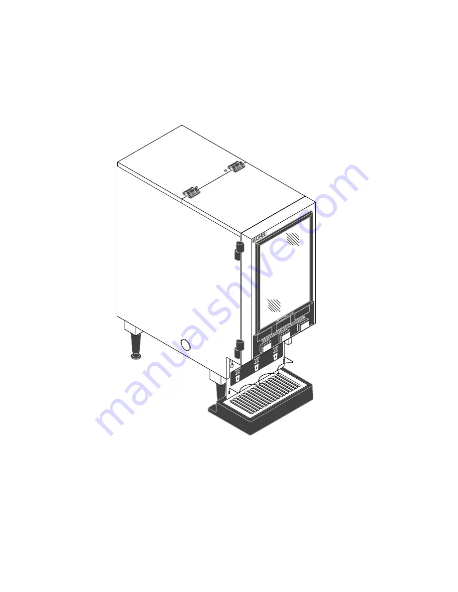
HC-2HC-3
(SERIAL # HC00025000 - UP)
Страница 1: ...ATING SERVICE MANUAL BUNN O MATICCORPORATION POST OFFICE BOX 3227 SPRINGFIELD ILLINOIS 62708 3227 PHONE 217 529 6601 FAX 217 529 6644 27591 0000 6 00 1996 Bunn O Matic Corporation HC 2 HC 3 SERIAL HC00025000 UP ...
Страница 2: ...D TO ANY IMPLIED WARRANTY OF EITHER MERCHANTABILITY OR FITNESS FOR A PARTICULAR PURPOSE The agents dealers or employees of Bunn are not authorized to make modifications to this warranty or to make additional warranties that are binding on Bunn Accordingly statements by such individuals whether oral or written do not constitute warranties and should not be relied upon The Buyer shall give Bunn prom...
Страница 3: ... 26525 0000 27620 0000 USER NOTICES Carefully read and follow all notices on the equipment and in this manual They were written for your protection All notices are to be kept in good condition Replace any unreadable or damaged labels 27591 061500 ...
Страница 4: ...al block as illustrated above 6 Connect the dispenser to the power source and verify the voltage at the terminal block Reinstall the side panel 7 If plumbing is to be hooked up later be sure the dispenser is disconnected from the power source If plumbing has been hooked up the dispenser is ready for Initial Fill Heat PLUMBING REQUIREMENTS This dispenser must be connected to a COLD WATER system wit...
Страница 5: ...er s with the dry product to be dispensed DISPENSER USE 1 Simply place a cup on the drip tray beneath the desired dispensing tip 2 Press the button to froth and dispense the beverage 3 Release the button when the cup is approximately 2 3 full and allow the mixing chamber to drain NOTE The mixing chamber must drain at the end of each dispense COLD BEVERAGE SET UP OPTIONAL Cold beverages may be disp...
Страница 6: ...ter exhausting the troubleshooting steps contact the Bunn O Matic Technical Service Department Inspection testing andrepairofelectricalequipmentshouldbeperformedonlybyqualifiedservicepersonnel All electronic components have 120 volt ac or 240 volt ac and low voltage dc potential on their terminals Shorting of terminals or the application of external voltages may result in board failure Intermitten...
Страница 7: ...d and white terminal and the black and white terminal on three wire 120 240 volt dispenser A3 Check the terminal block for 240 volts across the white and black terminal on two wire 240 volt dispenser B Check circuit breakers or fuses Refer to Service Dispense Switch for testing procedure See page 18 Refer to Service Dispense solenoid valve for testing proce dures See page 30 or 31 Refer to Service...
Страница 8: ...ly depending on local water condi tions Excessive mineral build up on stainless steel surfaces can initiate corrosive reactions result ing in serious leaks 2 Control thermostat mechanical or electronic REMEDY A Direction of flow arrow must be pointing towards dispenser B Remove the flow control and check for obstructions Clear or replace Inspect the tank assembly for excessive lime deposits Delime...
Страница 9: ...noid valve Hot or Cold 1 Level control board and probe 2 Solenoid valve Inlet 3 Overflow Protection Switch REMEDY Inspect the tank assembly for excessive lime deposits Delime as required Remove the dispense solenoid valve and clear any obstructions Rebuild or replace the valve if necessary See page 30 or 31 Refer to Service Level Control Board and Probe for testing procedures See page 26 Refer to ...
Страница 10: ...cle and check the water tempera tureimmediatelybelowthedispense tip with a thermometer A Reading for mechanical thermo statmodelsshouldbe180 Fto200 F seethermostattemperaturesettings decal in USER NOTICES on page 3 B Reading for electronic thermo stat should be185 F to 190 F Adjust the control thermostat to in crease or decrease the water tem perature Replace if necessary Referto Service WhipperMo...
Страница 11: ...t not exceed 90 psi 620 kPa Install a regulator if necessary to lower the working pressure to ap proximately 50 psi 345 kPa Remove and clean lime off the tank heater See page 33 Refer to Service Fan for testing procedures See page 19 Refer to Service Hopper Delay Board for testing procedures See page 22 Refer to Service Transformer for testing procedures See page 35 Refer to Service Lamp see page ...
Страница 12: ...d Level Probe 26 Limit Thermostat 27 Overflow Protection Switch 28 Rinse Run Switch 29 Solenoid Cold Drink Optional 30 Solenoid Dispense 31 Solenoid Inlet 32 Tank Heater 33 Tank Heater Switch 34 Transformer 240V Models Only 35 Whipper Motor 20 Wiring Diagrams 37 38 FIG 1 AUGER DRIVE COMPONENTS Location The auger components are located inside the bottom part of the hopper except for the auger drive...
Страница 13: ...disc assy from hopper 10 6 Remove auger 12 by pulling it out the front of the hopper 10 7 Remove auger drive shaft 5 by removing the retaining clip 6 from auger drive shaft 8 Slide washer 8 and auger drive shaft bracket 7 off of the auger drive shaft 5 9 Slide auger drive shaft 5 from auger drive shaft bushing 3 and remove from hopper 10 10 Remove locknut 9 from auger drive shaft bush ing 3 and re...
Страница 14: ... 8 32 screws securing the left auger motor to the auger motor mounting bracket or the four 8 32 screws securing the center and right auger motors to the auger motor mounting bracket 8 Remove auger motor and discard 9 Using three 8 32 screws on the left auger mo tor or four 8 32 screw on the center or right auger motor install new auger motor 17 on mounting bracket 16 10 Install dust seal 18 on aug...
Страница 15: ... models c 240 volts ac for two wire 240 volt models If voltage is present as described the ballast is oper ating properly If voltage is not present as described replace the ballast Removal and Replacement 1 Disconnect the wires from the ballast 2 Remove the two 8 32 keps nuts securing the ballast to the dispenser base 3 Remove and discard ballast 4 Install new ballast over the two weld studs on th...
Страница 16: ...models c 240 volts ac for two wire 240 volt models 5 Disconnect the dispenser from the power source If voltage is present as described the control thermo stat is operating properly Reinstall bulb into the tank If voltage is not present as described replace the ther mostat Electronic Thermostat Optional 1 Disconnect the dispenser from the power source 2 Disconnect the black wire of the control ther...
Страница 17: ...llary tube so that the tube and bulb inside the tank are in the vertical posi tion and away from any electrical connections 10 Refer to the illustration below and reconnect the wires NOTE The capillary tube must be clear of any electri cal termination and not kinked Electronic Thermostat Optional 1 Disconnect the wires from the thermostat 2 Remove the two 8 32 keps nuts securing the thermostat to ...
Страница 18: ...not present as described refer to the wir ing diagram and check the dispenser wiring harness 6 Check for continuity across the wires removed from the dispense switch with the switch in the ON pressed position Continuity must not be present when the switch is in the OFF released position If continuity is present as described reconnect the connector to the door interconnect wiring harness the switch...
Страница 19: ...val 2 Remove the four 8 32 screws securing the hop per mounting plate to the front panel and remove panel 3 Remove the four screws securing the fan mount ing plate to the dispenser front panel 4 Lift fan mounting plate out of the front panel far enough so the fan leads can be disconnected from the main wiring harness 5 Remove fan mounting plate fan and exhaust tube as an assembly 6 Remove the four...
Страница 20: ...oltmeter Connect the dis penser to the power source The reading must be Removal Cleaning and Replacement Refer to Fig 12 1 Open the dispenser door 2 Remove the steam collector 1 by pulling it for ward and at the same time twisting it clockwise 3 Pull the mixing chamber 2 out of the whipper chamber 4 a 120 volts ac for two wire 120 volt models b 120 volts ac for three wire 120 208 volt or 120 240 v...
Страница 21: ...ore reinstall ing in the dispenser 17 Place teflon washer into back opening of whipper chamberrecepticalandalignonenotchwithbump in the opening 18 Slide whipper chamber receptacle w seal on to the motorshaftandsecuretothefrontpanelusingtwo 6 32 screws 7 19 Slipo ring 5 ontothewhipperchamberreceptical 8 20 Pushfrother 6 ontothemotorshaft makingsure theflatinthefrother 6 linesupwiththeflatonthe moto...
Страница 22: ...oltmeter Press and hold the appropriate dispense switch Connect the dis penser to the power source After a delay of 7 seconds the indication must be a 120 volts ac for two wire 120 volt models b 120 volts ac for three wire 120 208 volt or 120 240 volt models c 240 volts ac for two wire 240 volt models 7 Disconnect the dispenser from the power source If voltage is present as described the hopper de...
Страница 23: ...e is not present as described refer to the wiring diagram and check the main wiring harness 5 Disconnect the wires from the switch termi nals 6 With the switch in the upper Cold position check for continuity between the center terminal and the bottom terminal With the switch in the down Hot position check for continuity between the center terminal and the upper terminal If continuity is present as...
Страница 24: ...r cover w reflector 4 lamp 3 lamp holders 2 and door wiring har ness as a assembly 6 Rotate lamp 3 90 and remove from lamp hold ers 2 7 Remove the 6 32 securing the lamp holder 2 to be removed remove lamp holder 2 and discard 8 Install new lamp holder 2 and secure with a 6 32 screw 9 Install lamp 3 into lamp holders 2 and turn 90 until the pins snap in place 10 Install upper door cover w reflector...
Страница 25: ...er If continuity is not present as described starter is operating properly Note Ifcontinuitytestareboth asdescribedandlamp does not light replace the starter socket Removal and Replacement Refer to Fig 16 1 Open dispenser door assy 1 2 Remove the six 8 32 screws securing the door bottom cover 5 to the door assy 1 3 Disconnect the plug on the starter socket and the connector on the door wiring harn...
Страница 26: ...models after a delay of approximately 5 seconds 8 Touch the free end of jumper wire to the dispenser housing The indication must be 0 9 Move the jumper wire away from the dispenser housing Theindicationmustagainbe120voltsac for two wire 120 volt models three wire 120 208 volt models three wire 120 240 volt models and 240 volts ac for two wire 240 volt models after a delay of approximately 5 second...
Страница 27: ... LIMIT THERMOSTAT FIG 19 LIMIT THERMOSTAT P1199 45 Location The limit thermostat is located in the center of the tank lid Test Procedures 1 Disconnect the dispenser from the power source 2 Disconnect both black wires from the limit ther mostat 3 Check for continuity across the limit thermostat terminals If continuity is present as described the limit thermo stat is operating properly If continuity...
Страница 28: ...om the liquid level board If continuity is not present as described replace the overflow protection switch Removal and Replacement 1 Disconnect the red leads from the overflow pro tection switch from the black wire from the termi nal block and the blue wire from the liquid level board 2 Remove the nut beneath the copper overflow cup 3 Remove the entire switch assembly from the cup 4 Place the new ...
Страница 29: ...resent as described the switch is operating properly If continuity is not present as described replace the switch Removal and Replacement 1 Open the dispenser door 2 Remove the facenut securing the run rinse switch to the dispenser front panel 3 Remove switch with wires attached from the back side of the front panel 4 Disconnect the wires from the switch and dis card the switch 5 Referring to the ...
Страница 30: ...l action Connect the brewer to the power source With HOT COLD switch in the COLD upper position press the left dispense switch and listen carefully in the vicin ity of the solenoid valve for a clicking sound as the coil magnet attracts 7 Disconnect the dispenser from the power source If the sound is heard as described and water will not pass through the solenoid valve there may be a block age in t...
Страница 31: ... and check dispenser wiring harness 5 Check for continuity across the solenoid valve coil terminals If continuity is present as described reconnect the white and white violet white blue or white brown wires to the solenoid If continuity is not present as described replace the solenoid valve 6 Check the solenoid valve for coil action Connect the dispenser to the power source With RUN RINSE switch i...
Страница 32: ... P1203 45 Location The inlet solenoid is located on the lower right side of the rear panel Test Procedures 1 Disconnectthedispenser fromthepowersource 2 Disconnect the white and violet wires from the solenoid valve 3 Check the voltage across the white and violet wires with a voltmeter Connect the dispenser to the power source The indication must be 120 volts ac for two wire 120 volt models three w...
Страница 33: ... noid 5 Using two 10 32 screws and nuts install new solenoid valve on rear panel 6 Securely fasten the water lines to and from the solenoid valve 7 Refer to Fig 28 when reconnecting the wires P1217 FIG 28 INLET SOLENOID VALVE TERMINALS TANK HEATER FIG 29 TANK HEATER P1199 40 Location The tank heater is located inside the tank and secured to the tank lid Test Procedure 1 Disconnect the dispenser fr...
Страница 34: ...emove the ten 8 32 nuts securing the tank lid to the tank 8 Remove tank lid with limit thermostat liquid level probe and tank heater as a assembly 9 Remove the two hex nuts securing the tank heater to the tank lid Remove tank heater with gaskets and discard 10 Install new tank heater with gaskets on the tank lid and secure with two hex nuts 11 Install tank lid with limit thermostat liquid level pr...
Страница 35: ...o fig 32 5 Push new switch through hole in the front panel and secure with face nut FIG 32 TANK HEATER SWITCH TERMINALS P1219 TANK HEATER SWITCH cont TRANSFORMER 240V TWO WIRE MODELS ONLY 1 2 3 FIG 33 TRANSFORMER P1289 Location The transformer is located behind the front cover just to the right of the ballest on the dispenser base Test Procedure 1 Disconnect the dispenser from the power source 2 D...
Страница 36: ...emoval and Replacement 1 Disconnect the wires from the transformer 2 Remove the two 8 32 keps nuts securing the transformer to the dispenser base 3 Remove and discard the transformer 4 Installnewtransformeroverthetwoweldstudson the dispenser base and secure with two 8 32 keps nuts 5 Refer to Fig 34 when renonnecting the wires 27591 031597 ...
Страница 37: ... 3 2 LIQUID LEVEL BOARD VIO WHI PNK 20 RED RED OVERFLOW SWITCH ELECTRONIC THERMOSTAT CONFIGURATION HEATER SW ELECTROMECHANICAL THERMOSTAT CONFIGURATION BLU BLK 16 BLU 16 BLK 16 BLK 16 TANK HEATER WHI 1 2 3 4 5 6 7 8 BLK WHI RED WHI VIO WHI BLU WHI GRN WHI GRN WHI HOPPER DELAY RED BLK BLK 4 1 4 1 BLK RED 4 1 BLK BLK BLK WHI DISPENSE SWITCH RIGHT MODELS HC 2 HC 3 DISPENSE SWITCH CENTER MODEL HC 3 ON...
Страница 38: ...ET BLK WHI WHI BLU PROBE 1 4 3 2 LIQUID LEVEL BOARD VIO WHI PNK 20 RED RED OVERFLOW SWITCH ELECTRONIC THERMOSTAT CONFIGURATION HEATER SW ELECTROMECHANICAL THERMOSTAT CONFIGURATION BLU BLK 16 BLU 16 BLK 16 BLK 16 TANK HEATER WHI 1 2 3 4 5 6 7 8 BLK WHI RED WHI VIO WHI BLU WHI GRN WHI GRN WHI HOPPER DELAY RED BLK BLK 4 1 4 1 BLK RED 4 1 BLK BLK WHI DISPENSE SWITCH RIGHT MODELS HC 2 HC 3 DISPENSE SWI...