Bunn CWT APS-DV Скачать руководство пользователя страница 1

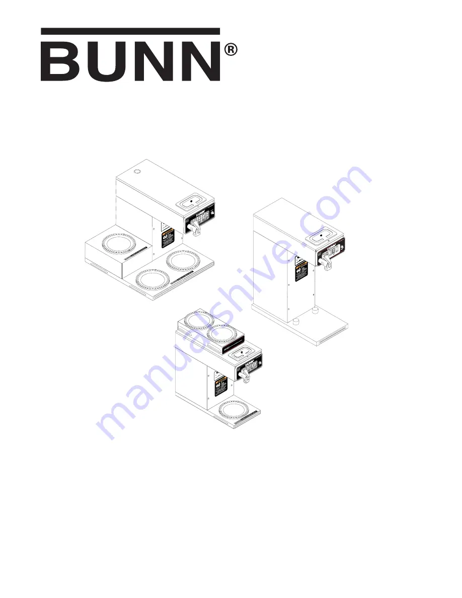
CWT -DV, CWT APS-DV,

CWTF-DV, CWTF APS-DV

OPERATING & SERVICE MANUAL

BUNN-O-MATIC CORPORATION

POST OFFICE BOX 3227

SPRINGFIELD, ILLINOIS 62708-3227

PHONE: (217) 529-6601    FAX: (217) 529-6644

www.bunnomatic.com

36102.0000A   09/03  ©2003 Bunn-O-Matic Corporation

Содержание CWT APS-DV

Страница 1: ...DV CWTF APS DV OPERATING SERVICE MANUAL BUNN O MATIC CORPORATION POST OFFICE BOX 3227 SPRINGFIELD ILLINOIS 62708 3227 PHONE 217 529 6601 FAX 217 529 6644 www bunnomatic com 36102 0000A 09 03 2003 Bun...

Страница 2: ...sted by BUNN shipping the defective equipment prepaid to an authorized BUNN service location and 3 receiving prior authorization from BUNN that the defective equipment is under warranty THE FOREGOING...

Страница 3: ...ow all notices in this manual and on the equipment All labels on the equipment should be kept in good condition Replace any unreadable or damaged labels 02765 0000 36102 090203 Optional Field Wiring 1...

Страница 4: ...15 6 A 2640 3400 W 1PH 3 Wire 60HZ 34955 0001 ONE WARMER MODELS 34955 0003 THREE WARMER BREWERS Optional Field Wiring 120 208 240 V 12 25 13 9 A 2440 3200 W 1PH 3 Wire 60HZ USER NOTICES CONT 120V 120...

Страница 5: ...rical service 4 Using a voltmeter check the voltage and color coding of each conductor at the electrical source 5 Remove the front access panel beneath the sprayhead to gain access to the terminal blo...

Страница 6: ...i 345 kPa The water inlet fitting is 1 4 flare NOTE Bunn O Matic recommends 1 4 copper tubing for installations of less than 25 feet and 3 8 for more than 25 feet from the 1 2 water supply line A tigh...

Страница 7: ...d flowing from the funnel It should be 64 ounces 9 If not adjust the brew timer as required SeeAdjustingBrewVolumes Start and measure another brew cycle 10 Repeat step 9 until 64 oz water volume is ac...

Страница 8: ...ntil the tank syphons down to its proper level Placing the switch in the ON upper position supplies power to enable the brew circuit on all brewers and the brew station warmer on CWT CWTF DV Models ST...

Страница 9: ...thout a supply of water Theuseoftwowrenchesisrecommendedwheneverplumbingfittingsaretightenedorloosened Thiswillhelp to avoid twists and kinks in the tubing Make certain that all plumbing connections a...

Страница 10: ...ice Timerfortesting procedures See page 26 and 27 Refer to Service Solenoid Valve for testing procedures See page 19 A Direction of flow arrow must be pointing towards brewer B Remove the strainer flo...

Страница 11: ...rly depending on local water condi tions Excessive mineral build up on stainless steel surfaces can initiatecorrosivereactionsresult ing in serious leaks REMEDY A Direction of flow arrow must be point...

Страница 12: ...alve 1 Dispenser 2 Timer 3 Solenoid Valve REMEDY Refer to Service Control Ther mostatfortestingprocedures See page 16 Thebrewermustbelevelorslightly lower in front to syphon properly Inspect the tank...

Страница 13: ...entle shak ing Placeanemptyfunnelonanempty dispenser beneath the sprayhead Initiate a brew cycle and check the water temperature immediately below the sprayhead with a ther mometer The reading should...

Страница 14: ...rewer is making unusual noises cont Low beverage serving tempera ture CWTF Only PROBABLE CAUSE 4 Tank Heater s 1 Warmer REMEDY Remove and clean lime off the tank heater s See page 20 Refer to Service...

Страница 15: ...specified COMPONENT ACCESS WARNING Disconnect the brewer from the power source before the removal of any panel or the replace ment of any component All components are accessible by the removal of the...

Страница 16: ...ts ac for two wire 120 volt models b 120 volts ac for three wire 120 208 volt models or 120 240 volt models 8 Disconnect the brewer from the power source Ifvoltageispresentasdescribed reinstallthecapi...

Страница 17: ...cribed the limit thermo stat is operating properly If continuity is not present as described replace the limit thermostat FIG 4 LIMIT THERMOSTAT P2759 40 SERVICE cont P1800 BLU to Control Thermostat B...

Страница 18: ...water supply 8 Refer to Fig 7 when reconnecting the wires Location TheON OFFswitchesarelocatedonthefrontofthe hood Test Procedure 1 Disconnect the brewer from the power source 2 Viewingtheswitchfromt...

Страница 19: ...witch in the ON upper position press start switch and listen carefully in the vicinity of the solenoid valve for a clicking sound as the coil magnet attracts 7 Disconnect the brewer from the power sou...

Страница 20: ...reconnect the blue wire to the top terminal and the white red wire to thebottomterminal Theswitchisoperatingproperly If continuity is not present as described replace the switch FIG 11 START SWITCH T...

Страница 21: ...f continuity is not present as described replace the open tank heater NOTE If the tank heater s remain unable to heat remove and inspect heater s for cracks in the sheath Removal and Replacement 1 Dis...

Страница 22: ...ual when reconnecting wires 16 Install fill basin secure with tank inlet fitting and gasket Insert water supply line through grommet in fill basin 17 Refer to Fig 13 when reconnecting the tank heater...

Страница 23: ...or reassembly 6 Disconnect the wires on the limit thermostat and the tank heater and the control thermostat early models 7 Gently pull the thermostat sensor and grommet from the tank lid 8 Insert a tu...

Страница 24: ...s 17 Reconnect the wires to the limit thermostat tank heater and the control thermostat Refer to limit thermostat tank heater and control thermostat sections in this manual when reconnecting wires 18...

Страница 25: ...reconnect the white wire and continue to Step 3 If continuity is not present as described replace the voltage selector switch 3 With the selector switch in the 120 208 240V position disconnect the wh...

Страница 26: ...yacrossthe thermal fuse terminals If continuity is present as described the thermal fuse is operating properly If continuity is not present as described replace the thermal fuse Removal and Replacemen...

Страница 27: ...t as described disconnect the brewer from the power source and replace the timer 7 With a voltmeter check the voltage across termi nals TL1 and TL4 when the ON OFF switch is in the ON position Connect...

Страница 28: ...me first check that the SET LOCK switch is in the SET position on the circuit board Place the ON OFF switch in the ON position press and hold the START switch until three distinct clicks are heard and...

Страница 29: ...terminals on the warmer element If continuity is present as described reconnect the wires on the warmer element If continuity is not present as described replace the warmer element Removal and Replace...

Страница 30: ...ON BLK BLK BLK BRN BLK BRN BLK BLK BLK BLK BLK BLU BLU WHI RED WHI HEATER SWITCH ON OFF SWITCH L1 BLU LIMIT THERMOSTAT READY INDICATOR GRN SW THERMOSTAT VIO VIO VIO VIO REAR WARMER FRONT WARMER LOWER...

Страница 31: ...I VIO 14 BLU 14 RED 14 TANK HEATER TANK HEATER SELECTOR SWITCH 10836 0010A 10 02 2001 BUNN O MATIC CORPORATION BLK BLK BLK BLK BLU BLU WHI RED WHI HEATER SWITCH ON OFF SWITCH L1 BLU LIMIT THERMOSTAT R...

Отзывы: