manualshive.com logo in svg
background image

www.homesystems-legrandgroup.com

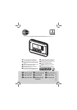
Installer manual

Thermostat with display

H/LN4691 - 0 674 59 - 64170

Содержание Legrand MyHome

Страница 1: ...www homesystems legrandgroup com Installer manual Thermostat with display H LN4691 0 674 59 64170 ...

Страница 2: ...Thermostat with display Installer manual ...

Страница 3: ... cooling function 12 5 2 Automatic changeover function 13 5 2 1 Automatic changeover in automatic or manual mode fixed set point 14 5 2 2 Automatic switching in Comfort Eco and Protection mode 15 5 3 Example of installation diagram 17 5 4 Operating modes 20 5 5 Fan coil speed 20 6 Programming 21 6 1 Display items 21 6 2 Brightness adjustment 24 6 3 Setting the temperature measurement unit 25 6 4 T...

Страница 4: ...ons Before proceeding with the installation it is important to read this manual very carefully The guarantee is automatically void in case of negligence improper use tampering by unauthor ised personnel The thermostat is only suitable for indoor installation 1 Introduction ...

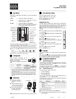
Страница 5: ...oom temperature measured the temperature set point set the fan coil fan speed the local contact status and the zone status The thermostat can be used in MyHOME temperature control systems MyHOME probe with cen tral unit hotel room systems or residential systems individual system The configuration can be done by connecting the configurators to the corresponding sockets in the back of the thermostat...

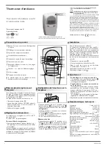
Страница 6: ...mode indicator 15 Window indicator active local contact according to the programming 16 Measured thermometer symbol On set thermometer symbol Off temperature indicator 17 Unit of measure C or F 2 Description MODE FAN 10 7 8 9 1 2 3 4 5 6 11 12 13 14 16 17 15 Auto Mode The remote setting control unit or supervision software follows In the case of MyHome systems the icons shown with asterisks do not...

Страница 7: ...HOME probe hotel thermostat or individual residential system HEAT definition of the type of heating load valves fan coil etc COOL definition of the type of cooling load valves fan coil etc PUMP selection of the pumps to control IN definition of the function performed by the contact connected to the thermostat For the configuration and setup of the local contact see the technical sheet ...

Страница 8: ...the next central unit set point change In comfort eco and antifreeze heat protection operation the control unit or other control device cannot change the mode To return to the control unit settings set the mode on automatic always using the sensor MODE key The systems consists of Power supply Actuators and pumps Temperature control central unit Thermostat with local contact for the detection of op...

Страница 9: ...g of consumptions therefore avoiding unwanted energy waste Home thermostat The third type of use as room thermostat manages the temperature control of an individual system without the need for additional control devices The systems consists of Power supply Actuators and pumps Thermostat with local contact for the detection of open windows PRI SCS E49 PRI 220 240 V 185 175 mA 50 60 Hz SCS 27 Vdc 60...

Страница 10: ...Fan coil speed From keypad From remote From keypad From remote From keypad 3 2 Function comparison table 3 Possible applications In the table below the first three columns show the functions which can be activated depending on the type of system in use while the last column defines which functions can be controlled locally by the keys on board the sensor The functions are set in the programming ph...

Страница 11: ...of the thermostat If no physical configurators are connected the device can be configured virtually by connecting it to a PC and using the dedicated MyHOME_Suite software In this way it is possible to simplify the configuration operations in large systems without the need to manually intervene on each device The advanced configuration offers more functions including being able to control several a...

Страница 12: ...If the measured temperature is lower than the reference value the heating system is activated and the corresponding symbol appears on the display When the temperature is reached the thermostat switches the zone off and the icon disappears Note The heating icon is always displayed Cooling function If the measured temperature is higher than the reference value the cooling system is activated and the...

Страница 13: ...ver mode cannot be configured physically but must be enabled during the advanced configuration using the MyHOME_Suite software This function can be used when it is necessary for the thermostat to automatically manage the changeover between heating and cooling and is for example useful in case of 4 tube fan coils Using the MyHOME_Suite software it is possible to set the range of temperature at diff...

Страница 14: ...the automatic changeover threshold has been set to 2 C Measured temperature Action T between set point automatic changeover threshold and set point automatic changeover threshold It maintains the current function T set point automatic changeover threshold It switches to the cooling function 2 T set point automatic changeover function It switches to the heating function 3 SET POINT COOLING HEATING ...

Страница 15: ...rature range settings The above example indicates the temperature set point pairs for Eco mode and Comfort mode The cooling system will activate when the temperature exceeds the upper set point while the heating system will activate when the temperature falls below the lower set point COOLING RANGE HEATING RANGE 32 22 24 14 SET POINT ECO SET POINT ECO 18 28 COOLING HEATING 32 22 24 14 SET POINT CO...

Страница 16: ...nstaller manual COOLING HEATING TIME TEMPERATURE HIGH SET POINT LOW SET POINT MEASURED TEMPERATURE The thermostat operates on two different set points high set point and low set point Example chart 5 Functions and operating modes ...

Страница 17: ...7 Vdc 600 mA SCS E49 MH201 MH201 E49 H LN4691 F430R8 BEDROOM1 PRI PRI 220 240 V 185 175 mA 47 63 Hz SCS 27 Vdc 600 mA SCS E49 MH201 MH201 E49 H LN4691 F430R8 BEDROOM2 PRI PRI 220 240 V 185 175 mA 47 63 Hz SCS 27 Vdc 600 mA SCS E49 MH201 MH201 E49 H LN4691 F430R8 BEDROOM3 PRI PRI 220 240 V 185 175 mA 47 63 Hz SCS 27 Vdc 600 mA SCS E49 MH201 MH201 2 3 4 5 6 1 DC In HUBSWITCH10 100 LANnetwork Compute...

Страница 18: ...d OUT 2 medium fan speed OUT 3 maximum fan speed OUT 4 heating solenoid valve OUT 5 cooling solenoid valve F430R8 M OUT3 OUT2 OUT1 N L1 L2 F430R8 OUT5 OUT4 OUT3 OUT2 OUT1 OUT5 OUT4 L N 230Vac BEDROOM 1 ACTUATOR ZA ZB N TYPE 0 1 1 BEDROOM 3 ACTUATOR ZA ZB N TYPE 0 3 1 BEDROOM 2 ACTUATOR ZA ZB N TYPE 0 2 1 BEDROOM 4 ACTUATOR ZA ZB N TYPE 0 4 1 ...

Страница 19: ...STAT ZA ZB TYPE HEAT COOL PUMP IN 1 1 7 CEN Thermostat configuration detail H LN4691 BEDROOM 2THERMOSTAT ZA ZB TYPE HEAT COOL PUMP IN 2 1 7 CEN BEDROOM 3THERMOSTAT ZA ZB TYPE HEAT COOL PUMP IN 3 1 7 CEN BEDROOM 4THERMOSTAT ZA ZB TYPE HEAT COOL PUMP IN 4 1 7 CEN ...

Страница 20: ...one off can only be set remotely or by contact With a short pressure 3 seconds maximum of the MODE key the system toggles between modes 5 Functions and operating modes 5 5 Fan coil speed If the thermostat is configured for the management of a fan coil type load by pressing the FAN key it is possible to scroll through the fan speeds available selecting one of the following values With MyHome suite ...

Страница 21: ...m C to F using the MyHOME_ Suite software or the user menu Configuration from central unit The CU symbol indicates that a session with a central unit or with a supervision software is running 6 1 Display items 6 Programming Temperature calibration see paragraph 6 4 The thermometer icon flashes quickly to indicate that calibration is being performed The temperature unit is set on C or F depending o...

Страница 22: ...s slowly to indicate that a remote configuration test is being completed No configuration The symbol flashes slowly to indicate that the thermostat is not configured Wrong configuration The symbol flashes quickly to indicate that the physical configuration of the thermostat is wrong 6 Programming ...

Страница 23: ...23 Thermostat with display Installer manual Error condition The display shows the Er symbol followed by a number 1 to 5 to indicate an error condition For more information see paragraph 7 3 ...

Страница 24: ...ars on the display Use the and keys to increase or decrease the brightness The display brightness can be adjusted on 10 levels Press the FAN key for at least 7 seconds Press the FAN key twice to confirm and quit the function NOTE the user setting procedure can be disabled using the software 6 Programming ...

Страница 25: ...unit appears on the display Use the and keys to change from one measurement unit to the other You can select setting the device on the temperature scale expressed in degrees C or F Press the FAN key for at least 7 seconds Press the FAN key to confirm and quit the function NOTE the user setting procedure can be disabled using the software ...

Страница 26: ...flashing quickly Keep pressing the keys after a further 7 seconds the thermometer icon stops flashing and the manual calibration is deleted The thermometer returns to the factory calibration settings Press and at the same time 7 seconds the thermometer icon starts flashing quickly Release the keys After releasing the keys it is possible to increase or decrease the temperature detected using and Wa...

Страница 27: ...play stops flashing the new set point is saved the set point stops flashing and remains on the display After this the display returns to showing the temperature detected The Comfort and Eco set points can only be modified if the loads have been assigned to the device otherwise they are blocked The current set point flashes for a few seconds During this time press or to change the temperature The d...

Страница 28: ...therwise required by current laws MODE FAN 150 cm 7 2 Technical data Power supply from BUS 18 27 Vdc AAbsorption 30 mA maximum backlighting while the keys are being pressed 16 mA backlighting during stand by 13 mA backlighting off Unit of measure C or F Operating temperature 0 40 C Dimensional data 2 flush mounted modules CE certification Standards IEC 60669 2 5 EN 50491 5 2 ...

Страница 29: ...utes the error screen will reappear With errors Er4 and Er5 the thermostat switches OFF and all the actions that can normally be performed by the user like the pressure of the keys are disabled Below is an example of an error screen Er1 No response from pump Er2 No response from actuator Er3 No response from slave probe Er4 Temperature sensor fault Er5 Internal error device NOTE if ER4 or a temper...

Страница 30: ...ent possibility of disabling change mode local settings calibration procedure and automatic fan coil speed proportional adjustment of the loads valves or fan coil speed key lock on the basis of the contact status and contact number management for advanced functions display backlighting adjustment Setting the temperature measurement unit by local keys TECHNICAL AFTER SALES SERVICE Legrand SNC only ...

Страница 31: ...31 Thermostat with display Installer manual ...

Страница 32: ...o com Legrand SNC 128 av du Maréchal de Lattre de Tassigny 87045 Limoges Cedex France www legrand com Legrand SNC reserves at any time the right to modify the contents of this booklet and to communicate in any form and modality the changes brought to the same ...

Отзывы: