background image

Transporting the Patient and Control Unit 

39 


Figure 33. Secure 

Transporting the Patient and Control Unit 

WARNING

Always use the handle when carrying the Control Unit.  Failure to do so 

could cause the Control Unit to be dropped resulting in bodily injury. 


WARNING

Before transporting the patient or moving the Control Unit, unplug the 

power cord from the wall outlet and secure the Connector Interface 

Cable near the patient.  Pulling of the EkoSonic™ Device may cause 

the device to dislodge, loss of access and patient injury. 


1.


Unplug AC power cord from the wall outlet. 

Note: 

The Control Unit will automatically switch to battery power and continue 

to provide ultrasound therapy, if the battery is adequately charged.  If the 

battery is not adequately charged ultrasound will stop and the Control Unit will 

turn OFF. 

2.


Secure the housing end of the Connector Interface Cable near the patient to 

prevent the EkoSonic™ Device from dislodging. 

3.


Secure the power cord. 

4.


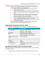
Use the carrying handle, the EKOS™ CU 4.0 Cart or an infusion stand to 

transport the Control Unit with the patient. 

  Ensure the Control Unit is securely attached to the EKOS™ CU 4.0 

Cart or stand. 

  Transport by holding the pole in the middle or using the provided 

handle if available to ensure the best control. 

  Do not allow the EKOS™ CU 4.0 Cart or infusion stand to tip.  

Содержание EKOS

Страница 1: ...EKOS Control System 4 0 Instructions for Use Caution Federal law restricts this device to use by or on the order of a physician Part number 8490 099 Rev J ...

Страница 2: ...rt Outside the U S Contact your local EKOS representative or call 1 425 415 3100 EKOS the EKOS Logo EkoSonic and MicroSonic are trademarks of EKOS Corporation a BTG International group company BTG and the BTG roundel logo are registered trademarks of BTG International Ltd All rights reserved In addition various other page elements may be trademarks claimed by EKOS including page headers icons grap...

Страница 3: ...ction 8 Screen Layout During Ultrasound Therapy 9 Color Coding Glossary 11 Safety Information 12 Warnings and Precautions 12 Power 17 Using AC Power and Charging the Battery 17 AC Power Battery Status Indicator 18 Battery Gauge 19 Low Battery Notification 20 Critically Low Battery 21 Battery Error 22 Battery Charging Indicator Control Unit Turned Off 23 Ultrasound Operation 25 Preparing for Ultras...

Страница 4: ...ontrol Unit 40 Storing the Control Unit 41 Disposal 42 System Information 42 Power Graph 43 Reading the Power Graph 43 Screen Layout Power Graph 44 Example Power Graphs 45 Snapshot 46 System Configurations 47 Audible Alert Volume 48 Screen Brightness 48 Selecting Language 48 Troubleshooting 49 System Errors 49 Channel Errors 51 Channel Messages 54 Symbols and Indicators 55 Specifications 62 System...

Страница 5: ...System 4 0 consists of the EKOS Control Unit 4 0 Control Unit Connector Interface Cable and power cord see Figure 1 EKOS Control Unit 4 0 Connector Interface Cable Infusion Catheter Connector EkoSonic Device Infusion Catheter Ultrasonic Core Ultrasonic Core Connector Figure 1 EkoSonic Endovascular System Power Cord Not Shown Housing End of Connector Interface Cable ...

Страница 6: ...e connected to AC power during operation but has an internal lithium ion battery to power the Control Unit temporarily during patient transport The Control Unit provides electrical energy to the transducers of the Ultrasonic Core and monitors the device temperature during ultrasound therapy The temperature data is used to automatically optimize ultrasound therapy to the treatment area The Control ...

Страница 7: ...ocally to increase the dispersion of the delivered solutions into the treatment region In addition to generating the prescribed ultrasound therapy profile the Control Unit continually monitors output power and temperature of the EkoSonic Device The system has safeguards to prevent deviation of these parameters from preset ranges Overview This section provides a basic orientation to the Control Uni...

Страница 8: ...eter IDDC Ultrasonic Core Connects to the Connector Interface Cable The Ultrasonic Core incorporates up to thirty fully encapsulated radiopaque piezoelectric ceramic ultrasound transducers along the distal length of the shaft The transducers emit ultrasound therapy radially along the axis of the treatment zone Note This is sometimes referred to as the MicroSonic Device MSD Front View Figure 2 Fron...

Страница 9: ...l Unit is OFF indicating battery charge status Note this icon is not visible when the Control Unit is ON When the Control Unit is connected to AC power Steady green indicates battery is fully charged Steady yellow indicates battery is charging Blinking red once per second indicates a battery error When the control Unit is not connected to AC power Blinking red once every 10 seconds reminds to plug...

Страница 10: ...e same time Ultrasound Start Button Starts energy transmission for a specific channel when pressed Ultrasound Stop Button Stops energy transmission for a specific channel when pressed Connector Interface Cable Receptacle For connecting the Connector Interface Cable s to the Control Unit Display Touch Screen Shows ultrasound and battery information and other messages settings and soft key buttons B...

Страница 11: ... using only a USB memory stick Equipotential Terminal In the absence of adequate grounding on the A C mains power line this terminal can be connected to a locally available external equipotential line to prevent danger caused by the difference in the potentials between this device and other devices Side View Figure 4 Side View of Control Unit Connector Interface Cable Attached for Storage Attachme...

Страница 12: ...uch screen provides menu tabs to navigate to other screens and indicates the current AC power battery status see Figure 5 Figure 5 Example Screen Prior to Connection Item Description Home Tab Displays cable connection and system instructions and ultrasound runtime Information Tab Displays Control Unit model number and software version Connector Interface Cable and device information and the EKOS h...

Страница 13: ...left side of the display messages and information associated with Channel B are provided in the message area on the right side of the display Screen Layout During Ultrasound Therapy During ultrasound therapy the display touch screen provides helpful information to monitor the ultrasound therapy This information is provided for each channel independently and channels can be interacted with separate...

Страница 14: ...ith Channel B are provided in the message area on the right side of the display Ultrasound Runtime Displays the current runtime for the channel Runtime is the length of time a device has delivered ultrasound therapy on a channel Time is displayed in Hours Minutes Seconds Running A green running indication is displayed when the ultrasound therapy is ON Additionally white bands animate in channel me...

Страница 15: ...icons Color Description Example GREEN Used to indicate the channel is ready running or generally without issue Note Ultrasound is ON for channel A in this example YELLOW Used to indicate further steps are required to start the ultrasound Note Ultrasound is OFF for channel A in this example RED Used to indicate there is an error or issue that requires further steps to resolve Note Ultrasound is OFF...

Страница 16: ...nt system may cause radio interference or may disrupt the operation of nearby equipment It may be necessary to take mitigation measures such as re orienting or relocating the Control Unit or shielding the location WARNING During normal use ultrasound energy may cause a temperature rise in the treatment zone There are temperature sensors in the EkoSonic Endovascular Device The EkoSonic Control Unit...

Страница 17: ...ing to the EkoSonic Device Failure to do so could result in patient infection WARNING Inspect all connectors cables and the Control Unit for damage prior to use If damaged e g exposed wires do not use and replace immediately WARNING Ensure all connectors are dry before connecting the Connector Interface Cable to the Control Unit or the Connector Interface Cable to the EkoSonic Device If connectors...

Страница 18: ...g the power cord from the wall outlet and secure the Connector Interface Cable near the patient Pulling of the EkoSonic Device may cause the device to dislodge loss of access and patient injury WARNING The Control Unit user interface presents a historical graph of the ultrasound power delivered The power data should not be used for diagnostic purposes Diagnosis of drug ultrasound therapy should al...

Страница 19: ... is adequate Failure to plug in the AC power after transport could result in the Control Unit turning OFF and delay of ultrasound therapy Caution After each use the Control Unit should be plugged into a hospital grade outlet to ensure the battery is recharged fully Failure to plug in the AC power after use could result in the battery not being fully charged and delay of ultrasound therapy Caution ...

Страница 20: ...rtable and mobile RF communications equipment can affect medical electrical equipment Use of the Control Unit with a power cord or accessory other than as specified in this Instructions for Use may result in increased electromagnetic interference EMI emissions or decreased immunity to EMI from other sources See Specifications Section This equipment generates uses and can radiate energy and if not ...

Страница 21: ...ould be plugged into AC power whenever possible during operation to ensure full output power Caution During use the Control Unit should remain plugged into a hospital grade outlet The battery is only intended to power the Control Unit for patient transport It is recommended that prior to transport the battery level be checked to ensure it is adequate Failure to plug in the AC power after transport...

Страница 22: ...ully Failure to plug in the AC power after use could result in the battery not being fully charged and delay of ultrasound therapy AC Power Battery Status Indicator When the Control Unit is turned ON and connected to AC power an indicator is displayed showing the connection and battery charging status Item Description Connected to AC power and battery is charging Connected to AC power and battery ...

Страница 23: ...attery a battery gauge shows the level of battery charge As battery charge decreases the battery gauge shows the decrease in battery charge The battery gauge with a red bar indicates a very low or fully depleted battery Item Description 76 100 51 75 26 50 16 25 0 15 If the battery is defective the battery icon is red with an X ...

Страница 24: ...ge with a red bar in the upper right corner of the display indicates the level of battery charge Connect to AC power to continue to use the Control Unit The message remains on the display and the tone repeats every minute until the Control Unit is connected to AC power or the Dismiss button on the touchscreen is pressed see Figure 8 Note If the Dismiss button was pressed and the battery charge lev...

Страница 25: ...ttery gauge with a red bar in the upper right corner of the display indicates the level of battery charge Ultrasound runtime for each channel is displayed during a critically low battery notification Immediately connect the Control Unit to AC power to prevent the unit from automatically shutting down in 3 minutes A countdown timer is displayed indicating how much time remains before the Control Un...

Страница 26: ...battery Contact your EKOS representative for information on replacing the battery The battery error notification is dismissed by pressing the Dismiss button on the touch screen The battery error notification appears whenever the Control Unit is connected to AC power is turned ON and a battery error is detected see Figure 10 If a battery error occurs when the Control Unit is not plugged into AC pow...

Страница 27: ... the Control Unit to indicate the battery charging status see Figure 11 Figure 11 Charging Indicator on Control Panel The charging indicator on the front of the Control Unit changes color to indicate the charging status If the battery reaches a critically low state the Control Unit enters battery saving mode and the charging indicator is not illuminated Charging Indicator ...

Страница 28: ... AC power Charge greater than 30 Blinking Audible Alert Blinking red once every 10 seconds and an audible alert indicates Control Unit is not connected to AC the battery has reached a low charge state and reminds to plug into AC power immediately Charge between 20 and 30 Not illuminated Battery icon not illuminated while the Control Unit is turned OFF indicates AC power is not connected and batter...

Страница 29: ...rs as marked and ensure connections are secure Failure to do so could result in electric shock or burn WARNING Avoid spilling fluids on the cables and Control Unit Do not immerse any portion of the cables or Control Unit in water or other fluids Fluids may cause the equipment to perform inaccurately or fail which could result in vascular injury Additionally fluids could result in fire or electric ...

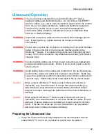
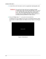
Страница 30: ... grade outlet could result in electric shock or burn Use of a non specified power cord could result in increased electromagnetic interference EMI emissions or decreased immunity to EMI from other sources 3 Press the Power button on the front of the Control Unit The EKOS boot screen followed by the logo screen display while the Control Unit performs its initial hardware and software test see Figure...

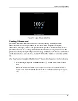
Страница 31: ...se packaged with the EkoSonic Device may still reference the previous Control System PT 3B and terminology All EkoSonic Devices will function as intended whether connected to a model PT 3B Control System or a Control System 4 0 After the physician has placed the EkoSonic Device into the patient do the following 1 If not already ON press the Power button on the front of the Control Unit When the Co...

Страница 32: ... Connect Interface Cable Screen Note If the Connector Interface Cable is already connected when the Control Unit is turned ON the channel is automatically activated and a connect device cables message is displayed see Figure 17 Similarly if the Connector Interface Cable is connected after the Control Unit is turned ON the channel is automatically activated and a connect device cables message is di...

Страница 33: ...ultrasound therapy to two devices connect one Connector Interface Cable to each receptacle see Figure 16 Figure 16 Connect Interface Cable Diagram After the Connector Interface Cable is connected to the Control Unit a connect message displays indicating to connect the device connectors to the Connector Interface Cable see Figure 17 A or B illuminates on the Connector Interface Cable housing once c...

Страница 34: ...nect the Infusion Catheter to the Connector Interface Cable see Figure 18 Figure 18 Connect Device Cables Diagram If the device is not properly connected a connect message displays indicating the specific device cable that needs to be connected Infusion Catheter or the Ultrasonic Core see Figure 19 and Figure 20 Ultrasonic Core Infusion Catheter ...

Страница 35: ...n the flow rates specified in the EkoSonic Device Instructions for Use 6 Secure the housing end of the Connector Interface Cable near the patient using standard hospital practices WARNING Secure device cables and the Connector Interface Cable using standard practices to preserve the integrity of the device minimize device movement at the insertion site and prevent device dislodgement If the Connec...

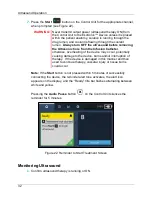
Страница 36: ...e overheating of the device may occur potentially causing damage to the device burns and or interruption of therapy If the device is damaged in this manner and then used to continue therapy vascular injury or tissue burns could occur Note If the Start button is not pressed within 5 minutes of successfully connecting the device the reminder alert tone activates the alert icon appears on the display...

Страница 37: ...therapy has been running for 23 minutes and 47 seconds see Figure 25 Hours Minutes Seconds Figure 25 Runtime Clock Note The runtime information is saved for the channel not for the device connected If the ultrasound therapy is stopped and restarted the timer will resume when the ultrasound therapy is started again If the device cables are disconnected e g patient transport and re connected the cha...

Страница 38: ...e Start button on the Control Unit for the appropriate channel The runtime will resume from the time at which it was stopped If the Start button is not pressed within 5 minutes the start reminder activates Completing Ultrasound Ultrasound therapy can be provided for an individual device on a single channel or two devices using both channels Because each channel operates independently ultrasound ca...

Страница 39: ...terface Cable 4 Press and hold the Power button for 3 seconds to turn OFF the Control Unit The shutdown screen displays as the Control Unit shuts down see Figure 30 Note If the Power button is pressed and held for 10 seconds or more it will force the Control Unit into a low power battery saving mode and data may be lost In this mode the battery charging indicator on the front panel will not illumi...

Страница 40: ...ector Interface Cable be placed on the side of the Control Unit during ultrasound therapy because the cord lengths are restricted 6 See Maintaining the Control Unit section for instructions on cleaning and storing the Control Unit Using an Infusion Stand or EKOS CU 4 0 Cart During use or storage the Control Unit can be attached to the custom designed EKOS CU 4 0 Cart or an infusion stand that meet...

Страница 41: ...to ensure the best control Always evaluate infusion stand stability for use environment after configuring for treatment Failure to follow these guidelines could result in the infusion stand tipping or equipment falling resulting in bodily injury Selecting the Appropriate Infusion Stand Use this guideline when selecting an infusion stand for mounting the Control Unit Component Specification Pole di...

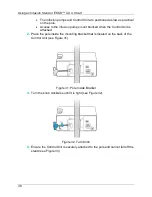
Страница 42: ...not blocked when the Control Unit is attached 2 Place the pole inside the mounting bracket that is located on the back of the Control Unit see Figure 31 Figure 31 Pole Inside Bracket 3 Turn the knob clockwise until it is tight see Figure 32 Figure 32 Turn Knob 4 Ensure the Control Unit is securely attached to the pole and cannot fall off the stand see Figure 33 ...

Страница 43: ...utlet Note The Control Unit will automatically switch to battery power and continue to provide ultrasound therapy if the battery is adequately charged If the battery is not adequately charged ultrasound will stop and the Control Unit will turn OFF 2 Secure the housing end of the Connector Interface Cable near the patient to prevent the EkoSonic Device from dislodging 3 Secure the power cord 4 Use ...

Страница 44: ...taining a sterile operating field after connecting to the EkoSonic Device Failure to do so could result in patient infection WARNING Thoroughly clean the Control Unit and Connector Interface Cable after each use When cleaning adhere to the following guidelines see Cleaning the Control Unit Section Follow all cleaning instructions provided in these Instructions for Use Turn off the Control Unit and...

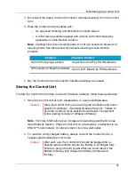
Страница 45: ...nd the Connector Interface Cable s follow these guidelines 1 Store the Control Unit at room temperature in a well ventilated area Caution Store the Control Unit in an area of good ventilation and under specified conditions See Specifications Section Failure to store the Control Unit as specified could result in equipment failure leading to delay of ultrasound therapy Note For more information abou...

Страница 46: ...r Interface Cable contain materials that must be disposed of in accordance with environmental protection requirements Do not dispose of the Control Unit or the Connector Interface Cable as unsorted municipal waste Please observe all national and local regulations In accordance with WEEE requirements before disposing of the Control Unit or the Connector Interface Cable contact EKOS Corporation for ...

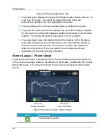
Страница 47: ...ber is not displayed if the transducer group in not present Power Graph The Control Unit monitors and presents a historical graph of the ultrasound power delivered to the EkoSonic Device s The percentage of the maximum average power actually delivered by each of the two channels is plotted over time on the power graph WARNING The Control Unit user interface presents a historical graph of the ultra...

Страница 48: ...ows the total runtime for the channel not for the device If possible always reconnect devices to the same channels they started on If two devices are switched from one channel to another the runtime will reflect the total amount of time that specific channel delivered therapy regardless of the device currently connected Screen Layout Power Graph Power Graph information is provided for each channel...

Страница 49: ...tted with a dashed line Example Power Graphs The power graph screen Figure 37 shows an example of what is displayed for two devices using two channels One device is connected to channel A and one device is connected to channel B Ultrasound therapy has been running for approximately 13 5 hours continuously for both devices and is currently on as indicated by the green channel icons and the 63 and 6...

Страница 50: ...nel therapy was started on If two devices are switched from one channel to another the runtime will reflect the total amount of time that specific channel delivered therapy regardless of the device currently connected Snapshot Every time the Control Unit is turned off and then back on e g turning off for patient transport a snapshot of the last power graph data will appear on the power graph scree...

Страница 51: ...on the Control Unit Caution When using the Control Unit care should be taken to optimize the display brightness and volume level for the use environment Failure to optimize could cause audible and visual information being missed resulting in delay of ultrasound therapy To access the system settings press the Settings tab on the display see Figure 40 Figure 40 Settings Menu Screen ...

Страница 52: ...er the brightness tap the left circle until the desired brightness is achieved Note The minimum setting reduces the brightness but does not completely darken the display Selecting Language 1 To view the list of available languages press the Select button 2 From the list of languages tap the desired language to highlight the selected language see Figure 41 If the desired language is not visible on ...

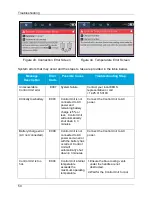
Страница 53: ...it temperature conditions and device cross connection errors When a system error occurs an error message with an alert icon displays and an audible tone sounds Read the message and follow the instructions to attempt to correct the error Press the Audio Pause button on the Control Unit to silence the alert tone for 5 minutes When the tone is silenced the alert icon on the display is crossed out If ...

Страница 54: ...t is not connected to AC power and remaining battery charge is 5 or less Control Unit will automatically shut down in 3 minutes Connect the Control Unit to AC power Battery charge error AC not connected E008 Control Unit is not connected to AC power and an error with the battery has occurred Control Unit will automatically shut down in 3 minutes Connect the Control Unit to AC power Control Unit is...

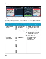
Страница 55: ...ound Channel Errors A channel error affects one specific channel and stops ultrasound therapy to the device associated with that channel The channel that does not have a channel error will not be interrupted or affected by the error Channel errors are related to channel errors device temperature errors cable errors and connection errors Channel errors can occur on both channels at the same time Wh...

Страница 56: ...0 E312 E322 Poor connection of the Infusion Catheter Infusion Catheter Connector is wet at the connection site 1 Disconnect the Infusion Catheter 2 Inspect for fluid or damage to the pins 3 Dry the Infusion Catheter connector if necessary 4 Reconnect the Infusion Catheter and ensure the connection is secure 5 Resume ultrasound Please contact EKOS Help Line E301 E303 E316 E317 E318 E319 E323 E324 E...

Страница 57: ...ompatible either catheter zone length and ultrasound zone length or working length Notify the physician Ensure the Ultrasonic Core is fully inserted in the catheter E314 The Ultrasonic Core is not fully inserted in the Infusion Catheter while ultrasound is running Ensure the Ultrasonic Core is fully inserted in the Infusion Catheter Resume ultrasound Check the Connector Interface Cable connection ...

Страница 58: ...and Ultrasonic Core The same error has occurred three times n a Control Unit has detected the same error three times in a row Contact your local EKOS representative or call 1 425 415 3100 Channel Messages A channel message is specific to a particular channel and indicates a task needs to be completed for the Control Unit to provide ultrasound therapy to that channel The message may also ask the op...

Страница 59: ...le Plug the catheter connector in the interface cable Press Apply to accept the new language and automatically restart control unit or press Cancel to keep the current language Symbols and Indicators The following symbols and indicators appear in these instructions on the Control Unit or on its components e g Connector Interface Cable Symbol Description Power Button Turns the Control Unit ON and O...

Страница 60: ...power Charge is greater than 30 Blinking red once every 10 seconds and an audible alert indicates Control Unit is not connected to AC and the battery has reached a low charge state and reminds to plug into AC power immediately Charge is between 20 and 30 Ultrasound Start Button Starts energy transmission for a specific channel when pressed Ultrasound Stop Button Stops energy transmission for a spe...

Страница 61: ...at shows the percentage of the maximum average power delivered for each channel Settings Tab Displays a configuration menu for setting audible alert volume screen brightness and language Connected to AC power and battery is charging Connected to AC power and battery is fully charged Battery charge remaining 76 100 Battery charge remaining 51 75 Battery charge remaining 26 50 Battery charge remaini...

Страница 62: ...time for the channel Runtime is the length of time a device has delivered ultrasound therapy on a channel Time is displayed in Hours Minutes Seconds Ultrasound therapy is ON When audio alert tone are on the alert icon displays When the audio alert tone are silenced the alert icon is crossed out indicating audio is silenced Decrease screen brightness Increase screen brightness Decrease audible tone...

Страница 63: ...ctured on Equipment was manufactured during the listed year Symbol for Electro static Discharge ESD sensitive equipment Equipment is resistant to ESD as required by BS EN 60601 1 2 However parts marked with this symbol could be damaged by direct application of electrical discharge The USB port is for use only by or at the instruction of authorized EKOS personnel for downloading procedure log files...

Страница 64: ...potential terminal It can be connected to a locally available external equipotential line to prevent danger caused by the difference in the potentials between this device and the other devices IPX2 Ingress Protection Rating for Control Unit IPX4 Ingress Protection Rating for Connector Interface Cable Symbol for Defibrillator Proof Type CF Equipment This equipment provides a degree of protection ag...

Страница 65: ...Symbols and Indicators 61 ...

Страница 66: ...r PZT Lead Zirconate Titanate Composition System Output Power Automatically controlled 100W pulse power maximum 70W average device power maximum for both channels 35W average device power maximum per channel Maximum Device Temperature 43 C Temperature Limit During normal use ultrasound therapy may cause a temperature rise in the treatment zone There are temperature sensors in the EkoSonic Device C...

Страница 67: ...D Ordering Information Product Catalog Number EKOS Control Unit model 4 0 600 40500 Connector Interface Cable 700 10410 Power Cord Power cord part numbers vary by geography For the part number for power cord for your geography please contact your local EKOS representative ...

Страница 68: ...ted RF emissions CISPR 11 Class A The Control Unit is suitable for use in all establishments other than domestic and may be used in domestic establishments and those directly connected to the public low voltage power supply network that supplies buildings used for domestic purposes provided the following warning is heeded Warning This equipment system is intended for use by healthcare professional...

Страница 69: ...ine s 2 kV line s to earth 1 kV line s to line s 2 kV line s to earth Mains power quality should be that of a typical commercial or hospital environment Voltage dips short interruptions and voltage variations on power supply input lines IEC 61000 4 11 5 UT 95 dip in UT for 0 5 cycle 40 UT 60 dip in UT for 5 cycles 70 UT 30 dip in UT for 25 cycles 5 UT 95 dip in UT for 5 s 5 UT 95 dip in UT for 0 5...

Страница 70: ...d strengths from fixed RF transmitters as determined by an electromagnetic site survey a should be less than the compliance level in each frequency range b Interference may occur in the vicinity of equipment marked with the following symbol NOTE 1 At 80 MHz and 800 MHz the higher frequency range applies NOTE 2 These guidelines may not apply in all situations Electromagnetic propagation is affected...

Страница 71: ...eparation distance according to frequency of transmitter m 150 kHz to 80 MHz d 1 17 P 80 MHz to 800 MHz d 1 17 P 800 MHz to 2 5 GHz d 2 33 P 0 01 0 12 0 12 0 23 0 1 0 37 0 37 0 74 1 1 17 1 17 2 33 10 3 70 3 70 7 37 100 11 7 11 7 23 3 For transmitters rated at a maximum output power not listed above the recommended separation distance d in meters m can be estimated using the equation applicable to ...

Отзывы: