


18
l
© Brüel & Kjaer Vibro GmbH
/
2 mm
ds822 ATEX /8.12.16/technical specifications subject to change/C105507.001/V02
EN
2 mm displacement sensor system series ds822 ATEX
| Installation
Instruction
measured. The displacement sensor is inserted and fixed in place by positioning it in the linear
measuring range (see drawing). To avoid damaging the sensor tip, the prescribed minimum
separation to the shaft (maximum displacement) must be maintained.
The minimum distance to the target must be selected so that even in the event of maximum
deflection of the shaft the distance (axial or relative to the shaft) does not fall below 0.4 mm.
In case of an axial measurement, the axial bearing clearance design and the current position of
the shaft must be considered in order to prevent damage to the sensor tip.
The displacement sensor system is fully assembled and connected to a power supply and
a monitoring system.
The physical separation should lie between 0.4mm and max. 2.4 mm.
Switch on the voltage for the driver.
You will obtain an output signal proportional to the measurement distance in the range -
2V…-18V. Adjust the separation of the sensor until the required output signal is present.
4.5
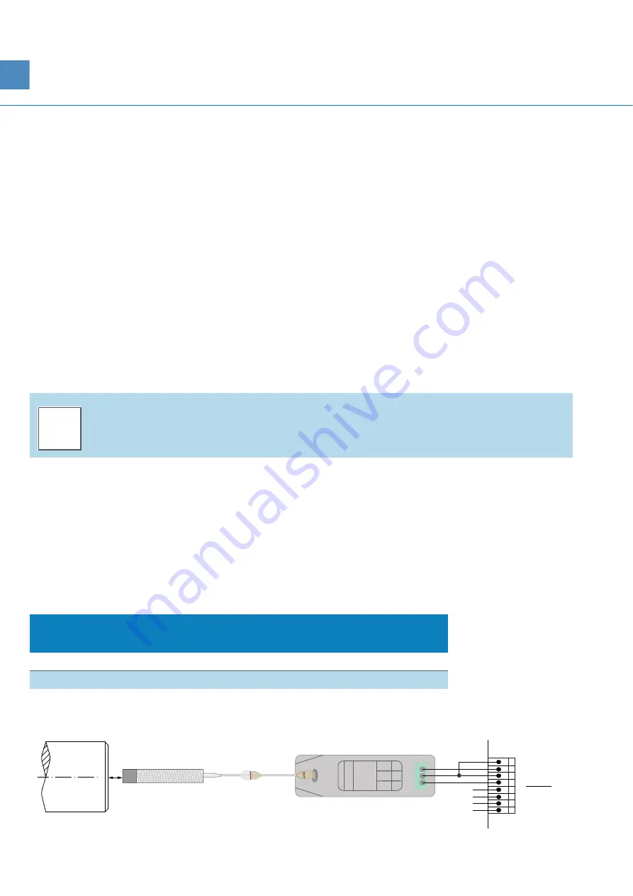
Electrical connection
Connect the driver with an electronic monitoring system (e.g. VC-6000) according to the draw-
ing below.When setting up your measuring system you should observe the following behavior of
the driver.
The heating effect of the driver electronics
During the warm-up phase the heating effect causes a drift in the static distance measurement.
Four wire connection
Connection of the driver to a monitoring system (VC-6000)
i
N
OTE
!
Use the characteristic curve U [GAP] to determine your minimum distance.
Displacement sensor
system
Operating time
Drift
5 m
1 h
1 μm
10 m
1 h
3 μm
1
Sensor
ds821-
od 130
2
3
4
-DC
COM
SIG
0,4...
max.
2,4 mm
5
6
7
8
0 V
-24 V
COM
SIG
A /
RC-600
VC-6000
B /
RC-600
/ Xx01
1
2
3
4
0 V
-24 V
COM
SIG


