


2-91
Confidential
4.10 Troubleshooting for PCB Problems
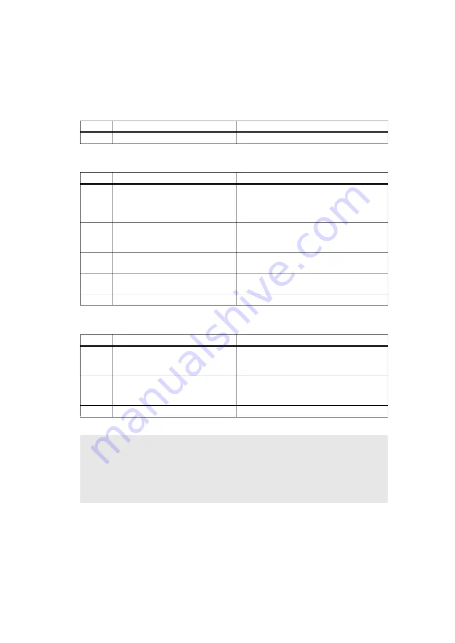
4.10.1 Main PCB failure
4.10.2 High-voltage power supply PCB failure
4.10.3 Low-voltage power supply PCB failure
<User Check>
- Turn the power switch OFF and then ON again.
- Install the latest firmware.
Step
Cause
Remedy
1
Main PCB failure
Replace the main PCB ASSY.
Step
Cause
Remedy
1
Connection failure of the high-
voltage power supply PCB harness
Check the harness connection between the
high-voltage power supply PCB and the
main PCB ASSY, and reconnect it if
necessary.
2
Contact failure of electrode
terminals of the high-voltage power
supply PCB
Clean the electrode terminals of the high-
voltage power supply PCB.
3
High-voltage power supply PCB
failure
Replace the high-voltage power supply PCB
ASSY.
4
Low-voltage power supply PCB
failure
Replace the low-voltage power supply PCB
ASSY.
5
Main PCB failure
Replace the main PCB ASSY.
Step
Cause
Remedy
1
Connection failure of the low-
voltage power supply PCB harness
Check the connection of the low-voltage
power supply PCB harness, and reconnect
it if necessary.
2
Low-voltage power supply PCB
failure
Replace the low-voltage power supply PCB
ASSY, and reset the irregular power supply
detection counter.
3
Main PCB failure
Replace the main PCB ASSY.
CAUTION:
• The irregular power supply detection error (error code EF00) occurs when there is a
large distortion in the power supply voltage supplied to the machine. In this case, if the
same power supply is used, the same error may occur even when the low-voltage
power supply PCB ASSY is replaced. Ask the user to review the installation
environment.
Содержание MFC-8510DN
Страница 27: ...Confidential CHAPTER 1 SPECIFICATIONS ...
Страница 43: ...Confidential CHAPTER 2 TROUBLESHOOTING ...
Страница 53: ...2 8 Confidential 2 2 2 Scanning Legal model Fig 2 5 A4 model Fig 2 6 Document feed path Document feed path ...
Страница 143: ...Confidential CHAPTER 3 DISASSEMBLY REASSEMBLY ...
Страница 154: ...3 8 Confidential Develop joint gear 37 Fig 3 4 Document scanner unit A4 model Fig 3 5 Legal model Fig 3 6 ...
Страница 155: ...3 9 Confidential Hinge ASSY L Fig 3 7 Hinge R Legal model only Fig 3 8 ...
Страница 165: ...3 19 Confidential 11 Main frame R Harness colors may be changed for any reason NCU earth harness BR Guides ...
Страница 201: ...3 55 Confidential 13 Remove the LCD and touch panel ASSY from the panel cover Fig 3 70 Touch panel ASSY Panel cover LCD ...
Страница 277: ...Confidential CHAPTER 4 ADJUSTING AND UPDATING SETTINGS AS REQUIRED AFTER PARTS REPLACEMENT ...
Страница 293: ...Confidential CHAPTER 5 SERVICE FUNCTIONS ...
Страница 300: ...5 5 Confidential Fig 5 1 ...
Страница 325: ...5 30 Confidential Fig 5 14 ...
Страница 327: ...5 32 Confidential Fig 5 15 ...
Страница 346: ...Confidential CHAPTER 6 WIRING DIAGRAM ...
Страница 348: ...6 1 Confidential 1 WIRING DIAGRAM Wiring diagram ...
Страница 349: ...Confidential CHAPTER 7 PERIODICAL MAINTENANCE ...
Страница 368: ...Confidential APPENDIX 1 SERIAL NUMBERING SYSTEM ...
Страница 372: ...Confidential APPENDIX 3 INSTALLING MAINTENANCE DRIVER ...


