3.15
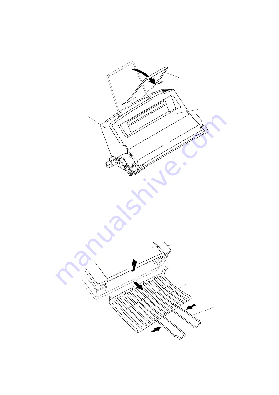
Tray Extension
(1) Put the tray extension assy down toward the front of the printer, and pull the bottom of
its both side legs outward to release it.
Fig. 3.16
3.16
Paper Eject Tray Assy
(1) Open the paper eject tray.
(2) Press the both sides of hinges of the paper eject tray inward to release it from the
holes on the top cover.
(3) Press the tray extension toward the arrays and remove it.
Fig. 3.17
-
1 6
-
Содержание HL-720
Страница 1: ...SERVICE MANUAL MODEL HL 720 730 730Plus R LASER PRINTER ...
Страница 36: ...II 19 1 3 10 Engine I O HL 720 Fig 2 21 shows the engine interface circuit Fig 2 21 ...
Страница 37: ...II 20 HL 730 730Plus Fig 2 22 shows the engine interface circuit Fig 2 22 ...
Страница 61: ... Fig 3 18 2 4 1 1 1 ...
Страница 92: ...SERVICE MANUAL MODEL HL 760 R LASER PRINTER ...
Страница 109: ...II 8 1 3 4 DRAM Two 4M bit DRAMs x 16bits are used as the RAM Fig 2 6 ...
Страница 113: ...II 12 1 3 10 Engine I O Fig 2 12 shows the engine interface circuit Fig 2 12 ...
Страница 114: ...II 13 1 3 11 Paper Feed Motor Drive Circuit Fig 2 13 ...
Страница 133: ...Appendix 2 Main PCB Circuit Diagram 1 3 CODE UK3227000 B48K272CIR 1 3 NAME ...
Страница 134: ...Appendix 3 Main PCB Circuit Diagram 2 3 CODE UK3227000 B48K272CIR 2 3 NAME ...
Страница 135: ...CODE UK3227000 B48K272CIR 3 3 NAME Appendix 4 Main PCB Circuit Diagram 3 3 ...


