HL-3450CN SERVICE MANUAL
4-5
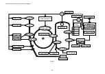
(5) Control
System
The control system consists of the following 4 (four) control parts and runs the printer
by processing the interface signals transmitted from the Host computer and interfacing
to the print, transfer, scanning and transport systems.
x
Sequence Control
x
Laser Control
x
Fusing Temperature Control
x
Interface Control
1.2
Basic Mechanism of Color Printing
1.2.1
Principle of color printing
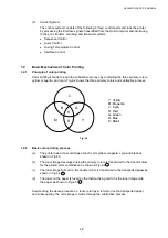
Color printing is made through the subtractive process by combining the three primary colors,
yellow, magenta, and cyan. Fig.4-2 shows the three primary colors and subtractive process:
C
B
K
G
M
R
Y
Y: Yellow
M: Magenta
C: Cyan
R: Red
G: Green
B: Blue
K: Black
Fig. 4-2
1.2.2
Basic color printing process
(a)
The printer has a toner cartridge of each color yellow, magenta, cyan and black as
shown in Fig.4-3.
(b)
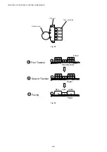
The toner image developed using the primary colors is transferred to the transfer drum
for the printed color combination as shown in Fig.4-4 a .
(c)
The toner image formed on the transfer drum is transferred to the transported paper as
shown in Fig.4-4 b .
(d)
The toner on the paper is fused by the thermal fixing unit to fix the toner image onto
the paper as shown in Fig.4-4 c .
Summarizing the above processes, a toner color layer is formed on the transported paper,
and subsequently, the color image is made through the subtractive process.
Содержание HL-3450CN Series
Страница 15: ...HL 3450CN SERVICE MANUAL xiii 3 Rating Label For US For Europe 4 Operation Label 5 Jam Label ...
Страница 17: ...HL 3450CN SERVICE MANUAL CHAPTER 1 PRODUCT OUTLINE ...
Страница 27: ...HL 3450CN SERVICE MANUAL CHAPTER 2 SPECIFICATIONS ...
Страница 39: ...CHAPTER 3 INSTALLATION ...
Страница 54: ...HL 3450CN SERVICE MANUAL CHAPTER 4 STRUCTURE OF SYSTEM COMPONENTS ...
Страница 87: ...CHAPTER 4 STRUCTURE OF SYSTEM COMPONENTS 4 34 Layout of Clutches 2 9 1 3 7 6 5 4 8 10 Fig 4 31 ...
Страница 104: ...HL 3450CN SERVICE MANUAL 4 51 Main PCB Circuit Diagram 1 8 CODE B512137CIR 1 8 LJ8907001 NAME ...
Страница 105: ...CHAPTER 4 STRUCTURE OF SYSTEM COMPONENTS 4 52 Main PCB Circuit Diagram 2 8 CODE B512137CIR 2 8 LJ8907001 NAME ...
Страница 106: ...HL 3450CN SERVICE MANUAL 4 53 Main PCB Circuit Diagram 3 8 CODE B512137CIR 3 8 LJ8907001 NAME ...
Страница 107: ...CHAPTER 4 STRUCTURE OF SYSTEM COMPONENTS 4 54 Main PCB Circuit Diagram 4 8 CODE B512137CIR 4 8 LJ8907001 NAME ...
Страница 108: ...HL 3450CN SERVICE MANUAL 4 55 Main PCB Circuit Diagram 5 8 CODE B512137CIR 5 8 LJ8907001 NAME ...
Страница 109: ...CHAPTER 4 STRUCTURE OF SYSTEM COMPONENTS 4 56 Main PCB Circuit Diagram 6 8 CODE B512137CIR 6 8 LJ8907001 NAME ...
Страница 110: ...HL 3450CN SERVICE MANUAL 4 57 Main PCB Circuit Diagram 7 8 CODE B512137CIR 7 8 LJ8907001 NAME ...
Страница 111: ...CHAPTER 4 STRUCTURE OF SYSTEM COMPONENTS 4 58 Main PCB Circuit Diagram 8 8 CODE B512137CIR 8 8 LJ8907001 NAME ...
Страница 112: ...HL 3450CN SERVICE MANUAL 4 59 Network Board PCB Circuit Diagram CODE LJ8107001 NAME B512058CIR ...
Страница 114: ...HL 3450CN SERVICE MANUAL 4 61 TAB2 HP TAB1 HN ACN4 ACN1 ACN3 ACN2 ACN5 Inlet Black White Power Switch Fig 4 40 ...
Страница 126: ...HL 3450CN SERVICE MANUAL CHAPTER 5 CONTROL PANEL OPERATION ...
Страница 173: ...HL 3450CN SERVICE MANUAL CHAPTER 6 PERIODIC MAINTENANCE ...
Страница 208: ...CHAPTER 7 DISASSEMBLY RE ASSEMBLY ...
Страница 264: ...HL 3450CN SERVICE MANUAL CHAPTER 8 TROUBLESHOOTING ...
Страница 310: ...HL 3450CN SERVICE MANUAL 8 47 5 IMAGE FAILURE 1 2 3 4 5 6 7 8 9 a 9 b 10 11 12 13 14 ...
Страница 311: ...CHAPTER 8 TROUBLESHOOTING 8 48 15 a 15 b 16 17 18 19 20 21 22 23 24 25 26 27 28 244m m 29 ...

