HL-3450CN SERVICE MANUAL
8-11
3.2
Inner Jam
Table 8-4
Problem Item
Step
Check Item
Result
Action
Open the transfer unit and
check.
1
Is there any paper inside the
unit?
YES
Remove the paper inside.
2
Is the transfer roller firmly
locked by the lock lever?
NO
Fix the transfer roller with
the lock lever.
Transfer Unit
3
Is the paper discharger unit
installed in place?
NO
Install the paper discharger
unit firmly in place.
4
Is there paper dust around the
registration roller?
YES
Clean the registration roller
with a cotton cloth.
5
Is the wire of the paper
discharger unit damaged?
YES
Replace the existing paper
discharger unit with a new
one.
6
Is the fusing unit installed in
place?
NO
Install the fusing unit firmly
in place.
Fusing Unit
7
Is there any paper trapped
between the rollers?
YES
Remove the trapped paper.
8
Is there fuser oil still in the oil
bottle?
NO
Replace the existing oil
bottle with a new one.
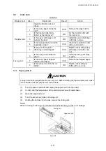
3.2.1 Paper guide D
CAUTION
Fusing unit and its peripheral parts are very hot. Before starting the replacement work, make
it sure that the unit and parts is well cooled down.
(1)
Turn the power switch off and unplug the power cord from the outlet.
(2)
Confirm that the temperature of the unit and parts is well cooled down.
(3)
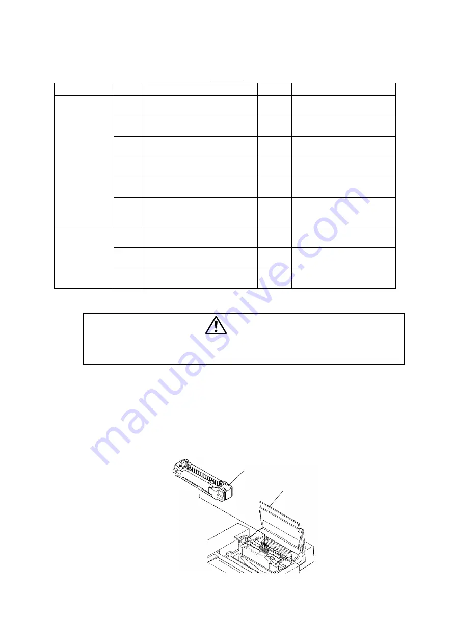
Open the paper exit unit.
(4)
Turn the set screws (2pcs.) of fusing unit.
(5)
Holding the handle of both sides, remove the fusing unit.
NOTE:
When removing the fusing unit, maintain the unit horizontally so that no oil leakage.
Fig. 8-2
Paper exit unit
Fusing unit
Содержание HL-3450CN Series
Страница 15: ...HL 3450CN SERVICE MANUAL xiii 3 Rating Label For US For Europe 4 Operation Label 5 Jam Label ...
Страница 17: ...HL 3450CN SERVICE MANUAL CHAPTER 1 PRODUCT OUTLINE ...
Страница 27: ...HL 3450CN SERVICE MANUAL CHAPTER 2 SPECIFICATIONS ...
Страница 39: ...CHAPTER 3 INSTALLATION ...
Страница 54: ...HL 3450CN SERVICE MANUAL CHAPTER 4 STRUCTURE OF SYSTEM COMPONENTS ...
Страница 87: ...CHAPTER 4 STRUCTURE OF SYSTEM COMPONENTS 4 34 Layout of Clutches 2 9 1 3 7 6 5 4 8 10 Fig 4 31 ...
Страница 104: ...HL 3450CN SERVICE MANUAL 4 51 Main PCB Circuit Diagram 1 8 CODE B512137CIR 1 8 LJ8907001 NAME ...
Страница 105: ...CHAPTER 4 STRUCTURE OF SYSTEM COMPONENTS 4 52 Main PCB Circuit Diagram 2 8 CODE B512137CIR 2 8 LJ8907001 NAME ...
Страница 106: ...HL 3450CN SERVICE MANUAL 4 53 Main PCB Circuit Diagram 3 8 CODE B512137CIR 3 8 LJ8907001 NAME ...
Страница 107: ...CHAPTER 4 STRUCTURE OF SYSTEM COMPONENTS 4 54 Main PCB Circuit Diagram 4 8 CODE B512137CIR 4 8 LJ8907001 NAME ...
Страница 108: ...HL 3450CN SERVICE MANUAL 4 55 Main PCB Circuit Diagram 5 8 CODE B512137CIR 5 8 LJ8907001 NAME ...
Страница 109: ...CHAPTER 4 STRUCTURE OF SYSTEM COMPONENTS 4 56 Main PCB Circuit Diagram 6 8 CODE B512137CIR 6 8 LJ8907001 NAME ...
Страница 110: ...HL 3450CN SERVICE MANUAL 4 57 Main PCB Circuit Diagram 7 8 CODE B512137CIR 7 8 LJ8907001 NAME ...
Страница 111: ...CHAPTER 4 STRUCTURE OF SYSTEM COMPONENTS 4 58 Main PCB Circuit Diagram 8 8 CODE B512137CIR 8 8 LJ8907001 NAME ...
Страница 112: ...HL 3450CN SERVICE MANUAL 4 59 Network Board PCB Circuit Diagram CODE LJ8107001 NAME B512058CIR ...
Страница 114: ...HL 3450CN SERVICE MANUAL 4 61 TAB2 HP TAB1 HN ACN4 ACN1 ACN3 ACN2 ACN5 Inlet Black White Power Switch Fig 4 40 ...
Страница 126: ...HL 3450CN SERVICE MANUAL CHAPTER 5 CONTROL PANEL OPERATION ...
Страница 173: ...HL 3450CN SERVICE MANUAL CHAPTER 6 PERIODIC MAINTENANCE ...
Страница 208: ...CHAPTER 7 DISASSEMBLY RE ASSEMBLY ...
Страница 264: ...HL 3450CN SERVICE MANUAL CHAPTER 8 TROUBLESHOOTING ...
Страница 310: ...HL 3450CN SERVICE MANUAL 8 47 5 IMAGE FAILURE 1 2 3 4 5 6 7 8 9 a 9 b 10 11 12 13 14 ...
Страница 311: ...CHAPTER 8 TROUBLESHOOTING 8 48 15 a 15 b 16 17 18 19 20 21 22 23 24 25 26 27 28 244m m 29 ...

