background image

9. ELECTRIC MECHANISM


HE-800B 


113 

9. ELECTRIC MECHANISM 


DANGER


Wait at least 5 minutes after turning off the power switch and disconnecting the power cord from the wall outlet 

before opening the face plate of the control box. Touching areas where high voltages are present will result in 

serious injury from electric shocks.


9-1. Precautions at the time of adjustment 


Electric shock 

Some large capacitors may have a high voltage remaining in them for up to 5 minutes after the power is turned off. To prevent 

electric shock, wait at least 5 minutes after the power is turned off before doing the following: 

• Opening and closing the control box


• Replacing fuses


• Separating and joining connectors


• Measuring resistance


• Doing anything wit

h a possibility of touching something inside the control box 

Some adjustments require measuring the voltage while the power is turned on with the control box kept open. 

In such a case, be careful not to touch any place other than that for the measurement. In addition, always keep in mind that a 

high voltage remains for about 5 minutes after power is turned off. 
 

Injury 

When separating or rejoining connectors, and measuring something, be careful not to cut your fingers on metal parts such as 

heat sinks and covers. 


Pay attention to the following when opening the control box for maintenance. 

Содержание HE-800B

Страница 1: ...HE 800B Please read this manual before making any adjustments ELECTRONIC DIRECT DRIVE LOCKSTITCH BUTTON HOLER SERVICE MANUAL ...

Страница 2: ...FETY INSTRUCTIONS below and the whole of this manual to understand this product before you start maintenance As a result of research and improvements regarding this product some details of this manual may not be the same as those for the product you purchased If you have any questions regarding this product please contact a Brother dealer ...

Страница 3: ...ch follow this term indicate situations where failure to follow the instructions could result in death or serious injury CAUTION The instructions which follow this term indicate situations where failure to follow the instructions may result in minor or moderate injury Symbols This symbol indicates something that you should be careful of The picture inside the triangle indicates the nature of the c...

Страница 4: ...and dew formation may cause problems with correct operation In the event of an electrical storm turn off the power and disconnect the power cord from the wall outlet Lightning may cause problems with correct operation Installation Machine installation should only be carried out by a qualified technician Contact your Brother dealer or a qualified electrician for any electrical work that may need to...

Страница 5: ... lubricating oil and grease so that they do not get into your eyes or onto your skin otherwise inflammation can result Furthermore do not drink the oil or eat the grease under any circumstances as they can cause vomiting and diarrhea Keep the oil out of the reach of children Maintenance and inspection Maintenance and inspection of the sewing machine should only be carried out by a qualified techni...

Страница 6: ...e guard B Finger guard C Thread take up cover D Motor cover E Slide cover 3 Be careful to avoid injury from the moving thread take up 7 4 Be careful not to get your hands caught when returning the machine head to its original position after it has been tilted 5 Be careful to avoid injury from the moving cutter 6 Be sure to connect the ground If the ground connection is not secure you run a high ri...

Страница 7: ...v HE 800B Oil tank accessory 4732M 4731M 4730M ...

Страница 8: ...lamp open at the sewing start Open 48 6 ASSEMBLY 49 6 1 Lower shaft and idle pulley mechanisms 50 6 2 Lower thread trimmer mechanism 52 6 3 Feed mechanism 54 6 4 Threading mechanism 57 6 5 Presser lifter mechanism 59 6 6 Needle zigzag mechanism 62 6 7 Cutter mechanism 64 6 8 Upper shaft and tension pulley mechanisms 67 6 9 Lubrication mechanism 69 6 10 Needle bar and thread take up mechanisms 75 6...

Страница 9: ...1 Troubleshooting flowchart 123 9 5 2 Problem solution and measures 127 10 TABLE OF ERROR CODES 142 11 TROUBLESHOOTING 148 11 1 Upper thread breakage 148 11 2 Skipped stitches 149 11 3 Uneven seams 1 At the sewing start 151 11 4 Uneven seams 2 Lower thread is lifted up at the sewing start 152 11 5 Uneven seams 3 Seam lifts up at the sewing start 152 11 6 Uneven seams 4 Uneven sewing pitch at the s...

Страница 10: ...motor driven mechanism Work clamp lifter mechanism Pulse motor driven mechanism Height of work clamp 13 mm max adjustable Cutter drive method Double position solenoid Lower thread holding device Standard equipment Bobbin presser Standard equipment Standard sewing pattern 21 Memory pattern 50 Max number of stitch 999 stitches program Overall cycle program stitch no 3 000 stitches Needle 2 3 Schmetz...

Страница 11: ...ht bar tack Radial rectangle Round rectangle Eyelet rectangle Rectangle radial Round radial Eyelet radial Rectangle round Radial round Eyelet round Rectangle tapertack Radial taper tack Round taper tack Eyelet taper tack Rectangle tack Radial tack Round tack Eyelet tack Rear tack Front tack ...

Страница 12: ...cords are used Carrying the machine The machine should be carried by the arm by two people as shown in the illustration Tilting back the machine head 1 Pack away any tools which are near the table 2 Secure the foot A so that the table will not move and then pull the arm with both hands to tilt back the machine head While supporting the arm with both hands gently lower it Returning the machine head...

Страница 13: ... Instruction Manual 4 Output check function Refer to 3 8 Output checking method 2 Memory switch setting mode Advanced Refer to 3 3 Setting memory switches Advanced 5 Software version display function Refer to 3 9 Confirming software version 3 Input check function Refer to 3 7 Input checking method 6 Error log display function Refer to 3 6 Checking the error history 2593B 0600D 0601D 0604D 0602D 06...

Страница 14: ... 10 Protection settings 8 Treadle position adjustment mode Refer to 7 22 Standard settings for treadle depression stroke 11 Version update Refer to 4 11 Updating the control program version 9 Upper shaft motor standard position adjustment mode Refer to 7 20 Adjusting the upper shaft motor reference position 0607D 0610D 0608D 0611D 0609D ...

Страница 15: ...f advanced functions This list shows the key operations for using advanced functions 1 Lower thread counter setting mode Refer to the CD Instruction Manual 2 Production counter setting mode Refer to the CD Instruction Manual 0612D 0613D 0614D ...

Страница 16: ... like to change the setting for 3 Change the setting value 3 When the setting value is changed 3 will start flashing If you would like to return the setting to the default value press the RESET key 4 Apply the changed setting The setting for the memory switch will be stored and 3 will stop flashing and illuminate steadily 5 To change the settings for other memory switch Nos repeat the operations i...

Страница 17: ...l optional part this number will not be displayed OFF Pausing is not allowed ON Pausing is allowed ON OFF OFF 053 Work clamp operation when using a triple pedal When using a treadle this number will not be displayed Refer to P 15 Neutral indicates that the work clamp is at the neutral position 1 Remains lowered even when the work clamp switch is released intermediate lowering disabled and starting...

Страница 18: ...eed becomes faster 4 to 4 0 062 Thread trimming speed Thread trimming speed becomes slower Thread trimming speed becomes faster 4 to 4 0 Sewing machine motor settings 100 to 199 No Setting items Setting range Default value 150 Automatic needle lifter operation ON OFF OFF If the pulley is at the needle up stop position during needle bar and work clamp home position detection a needle up error will ...

Страница 19: ...written from SD card Operation panel settings 300 to 399 No Setting items Setting range Default value 300 Parameter number assignment for FUNC key Functions can be assigned to the FUNC key to make it operate as a seventh shortcut key OFF No assignment The help screen is displayed while the FUNC key is pressed 1 to 60 When the FUNC key is pressed the parameter setting screen for the number which ha...

Страница 20: ...or checking OFF Error checking is not carried out emergency measures when there is a sensor problem ON Error checking enabled ON OFF ON 552 Upper thread tightening when sewing underlays OFF Upper thread is not tightened ON Upper thread is tightened ON OFF OFF 554 Using the thread breakage detector OFF Thread breakage detector is not used ON Thread breakage detector is used ON OFF ON 555 Number of ...

Страница 21: ... can be corrected in the Y feed direction Settings can be made in units of 0 025 mm When is selected the cutting position moves further to the back 0 800 to 0 800 0 750 Continuous sewing permission for administrator OFF Disabled Continuous sewing forbidden ON Sewing operation is repeated while the treadle is being depressed to 2nd step NOTE This setting is test operation mode for use by an adminis...

Страница 22: ...3 specifications 4 2 853 1 Language 0 English 1 Japanese 2 Chinese 0 to 2 China 2 Europe 0 Other 0 3 1 This is not initialized during initialization mode Also not overwritten from SD card 2 The initial value is determined by the machine head specifications at the time of shipment from the factory 3 The initial value is determined by the shipping destination at the time of shipment from the factory...

Страница 23: ...epressed backward Neutral 1st step 2nd step 1 Work clamp raised Work clamp neutral position Work clamp maximum drop Sewing machine start 2 Work clamp raised Work clamp neutral position Work clamp intermediate drop Work clamp maximum drop sewing machine start Raised Depressed further Releas Depres 1st step Neutral 1st step 2nd step Depress backward Release 1st step 2nd step Neutral Depressed Insert...

Страница 24: ...s 4 Work clamp lifts Work clamp neutral position Work clamp maximum drop Sewing machine starts 5 Work clamp lifts Work clamp neutral position Sewing machine starts 6 Work clamp lifts Work clamp neutral position Work clamp maximum drop Sewing machine starts 7 Work clamp lifts Work clamp maximum drop Sewing machine starts 8 Work clamp lifts Work clamp maximum drop Sewing machine starts The start swi...

Страница 25: ...n in the error history and so they will not be displayed 2 Press the or key 2 to switch the error history sequentially Up to 96 histories 01 to 96 are stored in order starting from the newest No 01 represents the newest error If there are no error codes E will be displayed While the FUNC key 3 is being pressed the error codes will be removed from the display and the production counter when the err...

Страница 26: ...nsor position This lets you check if the CPU is reading signals from the keys and the sensors correctly 1 While pressing the key 1 turn on the power switch Item numbers item names and input statuses will be displayed on the screen 2 Press the key 1 or the key 2 to select the desired item number 3 Refer to the input check list to check the key and sensor responses 4 When returning to normal operati...

Страница 27: ...s on when moved to the inside 5 Y feed axis motor encoder counter value Move the feed arm 1 manually Goes down when moved to the inside When the power is turned on the position will be 0 6 ON OFF Work clamp motor home position sensor position Move the trimmer driving arm 1 manually Turns on when moved in the direction of the arrow 7 Work clamp motor encoder counter value Move the trimmer driving a...

Страница 28: ... breakage detection guide is moved to the right 19 ON OFF Needle up signal Turn the pulley by hand ON in the needle up region OFF in any other region 20 0 to 359 Upper shaft 360 degree rotation signal Turn the pulley by hand Increases when turned forward counterclockwise rotation 21 ON OFF key 22 ON OFF key 23 ON OFF ENTER key 24 ON OFF Shortcut 1 key 25 ON OFF Shortcut 2 key 26 ON OFF Shortcut 3 ...

Страница 29: ...hile pressing the key 1 turn on the power switch 2 Depress the treadle to the 2nd step Start switch for a triple pedal The needle bar and the work clamp will move to the home position Item numbers and item names will be displayed on the screen 3 Press the key 2 or the key 1 to select the desired item number 4 The operations for item codes 51 to 53 can be checked by pressing the or key 3 The operat...

Страница 30: ...u can press the and keys to change the speed between 1000 sti min and 4000 sti min 55 The buzzer will sound for 0 7 second then the work clamp will move 15 mm back and forth and then the cutter will operate 56 The tension release solenoid will turn on 57 The panel indicators will illuminate in order CAUTION AUTO TEST COPY 58 The buzzer will sound 59 Option output 1 will turn on 60 Option output 2 ...

Страница 31: ...n the menu display 2 2 The PROGRAM No display 4 will change as follows each time the or key 3 is pressed USR MN Main control program MT Motor control program PL Panel control program IPL MN Main IPL MT Motor IPL PL Panel IPL 3 Press the TEST key 5 to return to the normal display The sewing machine will switch to home position detection standby 0621D 0622D ...

Страница 32: ...rtain operations are disallowed depending on the protection level Protected items have been preset for each level Refer to Table of protection levels and corresponding protected items on page 25 5 You can set the protection level for each of the 11 items individually Set to ON disallowed or OFF allowed for each item All items are set to OFF at the time of shipment from the factory 3 Press the ENTE...

Страница 33: ...nd the TEST key 2 and the ENTER key 3 turn on the power switch The previous starting method A B or B will appear in the menu display The method is set to A B at the time of shipment from the factory 2 Press the or key 4 to select the next starting method Starting method Details A B Protect setting mode can be started using either Method A or Method B B Protect setting mode can only be started usin...

Страница 34: ...ard memory switch settings Administrator memory switch settings Changing the program number Changing the sewing speed Parameters relating to sewing speed Program editing Program copy mode Cutter operation Production counter editing Lower thread counter editing Resewing after sewing is interrupted Home position adjustment Upper shaft motor reference position adjustment Treadle position adjustment ...

Страница 35: ...eformatted The recommended SD cards are those sold by SanDisk and Panasonic Cards from other manufacturers may use different formatting methods and may not work correctly as a result For additional information refer to the instruction manual included with the SD cards that you have purchased This product is compatible with SD cards that have been formatted using the FAT16 32 method Cards that have...

Страница 36: ... write mode The initial status is parameter reading Refer to Read write menu list below 4 Select the read write menu Press the or key Read write mode list Menu Details R1 Program data parameters is read from the SD card W2 Program data parameters is written to the SD card R3 Memory switch data is read from the SD card W4 Memory switch data is written to the SD card R5 All sewing machine data progr...

Страница 37: ...he sewing machine s memory The R W indicator will flash and OPERATING will be displayed If no program data exists on the SD card an error buzzer will sound 3 When the display returns to the status in step 1 reading of the program data is complete If you would like to read more data press the or key to select the read write menu and then read the data 4 Exit data read write mode Press any one of th...

Страница 38: ...am data parameters will be copied to the SD card The R W indicator will flash and OPERATING will be displayed 3 When the display returns to the status in step 1 writing of the program data is complete If you would like to read more data press the or key to select the read write menu and then read the data 4 Exit data read write mode Press any one of the following four keys to exit data read write ...

Страница 39: ...nternal memory The R W indicator will flash and OPERATING will be displayed If no memory switch data exists on the SD card an error buzzer will sound 3 When the display returns to the status in step 1 reading of the memory switch data is complete If you would like to read more data press the or key to select the read write menu and then read the data 4 Exit data read write mode Press any one of th...

Страница 40: ...ch data will be copied to the SD card The R W indicator will flash and OPERATING will be displayed 3 When the display returns to the status in step 1 writing of the memory switch data is complete If you would like to read more data press the or key to select the read write menu and then read the data 4 Exit data read write mode Press any one of the following four keys to exit data read write mode ...

Страница 41: ...ternal memory The R W indicator will flash and OPERATING will be displayed If no program data or cycle program data or memory switch data exists on the SD card an error buzzer will sound 3 When the display returns to the status in step 1 writing of the memory switch data is complete If you would like to read more data press the or key to select the read write menu and then read the data 4 Exit dat...

Страница 42: ...ta and memory switch data will be copied to the SD card The R W indicator will flash and OPERATING will be displayed 3 When the display returns to the status in step 1 writing of the sewing machine data is complete If you would like to read more data press the or key to select the read write menu and then read the data 4 Exit data read write mode Press any one of the following four keys to exit da...

Страница 43: ... data will be copied to the SD card The R W indicator will flash and OPERATING will be displayed 3 When the display returns to the status in step 1 writing of the error log data is complete If you would like to read more data press the or key to select the read write menu and then read the data 4 Exit data read write mode Press any one of the following four keys to exit data read write mode 2414B ...

Страница 44: ...witch Keep pressing the key until a beep is heard 4 Press the or key to select the program to be updated Types Version No Main 1 Mn Motor 2 Mt Panel 3 PL The initial status is for the main program to be selected If there is no program to be updated which is stored on the SD card will appear in the menu display 5 Press the ENTER key The buzzer will sound and updating of the program version will sta...

Страница 45: ... only They do not represent the flow of operations 5 1 Needle bar and thread take up mechanisms 1 Motor 2 Upper shaft 3 Needle bar crank 4 Needle bar crank 5 Thread take up crank 5 Thread take up assembly 6 Slide block 7 Needle bar clamp 8 Needle bar The mechanisms operate in the order of the numbers given in the illustrations 0641D Rotation direction ...

Страница 46: ...ANICAL DESCRIPTIONS 37 5 2 Upper shaft lower shaft and rotary hook mechanisms 1 Motor 2 Upper shaft 3 Joint assy 4 Timing belt 5 Timing pulley 6 Lower shaft 7 Rotary hook joint 8 Rotary hook 0642D Rotation direction ...

Страница 47: ...E 800B 5 MECHANICAL DESCRIPTIONS 38 5 3 Needle zigzag mechanism 1 Pulse motor 2 Zigzag connecting rod 3 Zigzag lever 4 Zigzag lever F assembly 5 Needle bar bracket slide block 6 Needle bar bracket 0643D ...

Страница 48: ...lse motor 2 Driving gear 3 Presser driving arm 4 Presser foot lifter connecting rod 5 Knee lifter lever 6 Upper thread trimmer driving link 7 Knee lifter lever 8 Presser bar guide bracket assembly 9 Presser bar 10 Presser roller bracket 11 Feed arm support 12 Work clamp 0644D ...

Страница 49: ...ulley A 3 Timing belt 4 Feed arm support base 5 Feed arm 5 Length feed plate 6 Work clamp 5 6 Cutter mechanism 1 Cutter solenoid 2 Cutter link bracket 3 Slide block 4 Cutter driving arm 5 Cutter driving link 6 Driving shaft holder assembly 7 Cutter driving shaft 0645D 0646D ...

Страница 50: ...HE 800B 5 MECHANICAL DESCRIPTIONS 41 5 7 Thread breakage detection mechanism 1 Thread guide 2 Thread breakage perceiving shaft 3 Cutter bar fixed plate assembly 4 Sensor 0647D ...

Страница 51: ...ion release link 4 Tension release pin 5 Tension disc pressers Tack tension control 1 Pulse motor 2 Driving gear 3 Presser driving arm 4 Presser foot lifter connecting rod 5 Knee lifter lever 6 Upper thread trimmer driving link 7 Tension release driving lever 8 Tension release shaft 9 Tension release cam 10 Tension release pin 11 Tension disc pressers 0649D 0648D ...

Страница 52: ...he presser foot drops The upper thread scissors retract and the presser foot lifts Presser foot drops Presser foot lifts After 1 5 2 5 mm of feed the upper thread scissors gradually start to open After approximately 4 6mm of feed the upper thread scissors are fully open Sewing ends The upper thread scissors move forward Upper thread trimming The upper thread is clamped and cut 1739B ...

Страница 53: ...riving link 2 Driving gear 3 Presser driving arm 4 Presser foot lifter connecting rod 7 Trimmer driving lever 7 Driving lever 5 Knee lifter lever 8 Longitudinal feed arm 8 Trimmer driving arm 9 Upper thread trimmer lever 10 Setting plate 11 Upper thread trimmer assembly 0652D ...

Страница 54: ...HE 800B 5 MECHANICAL DESCRIPTIONS 45 5 9 1 Upper thread scissors Gradually opens 1 Opening cam 2 Scissors M 0654D 0653D ...

Страница 55: ...CHANICAL DESCRIPTIONS 46 5 9 2 Upper thread scissors Open 1 Cam 4 Back stopper 1 Feed arm 2 Back plate 5 Upper thread trimmer lever 2 Extension spring 3 Stop plate 6 Upper thread trimmer assembly 0658D 0657D 0656D ...

Страница 56: ...lever 6 Lower thread trimmer cam 7 Lower thread trimmer cam connecting rod 8 Lower thread trimmer cam connecting rod 9 Lower thread trimmer link 10 Lower thread trimmer connecting rod 11 Knife driving lever 12 Collar 12 Fixed knife set 13 Lever 14 Lower thread retainer 15 Lower thread clamp plate 16 Lower thread presser 17 Fixed knife set 0659D Lower thread retainer Lower thread trimmer ...

Страница 57: ...0B 5 MECHANICAL DESCRIPTIONS 48 5 10 1 Lower thread clamp open at the sewing start Open 1 Feed guide shaft B 1 Spring 2 Roller 2 Lower thread presser 3 Opening plat 4 Collar 5 Lower thread clamp plate 0661D ...

Страница 58: ...he grease under any circumstances as they can cause vomiting and diarrhea Keep the oil out of the reach of children When replacing parts and installing optional accessories be sure to use only genuine Brother parts Brother will not be held responsible for any accidents or problems resulting from the use of non genuine parts If any safety devices have been removed be absolutely sure to re install t...

Страница 59: ...escriptions on the next page for details on A to G in the illustration 0663D Gently push while installing A C D E F G Insert as far as the bottom of the hole Set so that the worn surface is facing toward the bush Install so that there is no play B Assemble each part in order of the numbers ...

Страница 60: ...28 Spring 29 Screw a Rubber plugs 4 pcs b Oil feeding pipe 4 pcs c Bearing A B C D Check that the spring 20 is not compressed when the wick 21 is pulled in the direction of the arrow Push the end of the felt 22 into the hole in the bush 5 and stop it from turning E F G As a guide for the lubrication amount the optimum position can be obtained if the screw 29 is tightened as much as possible and th...

Страница 61: ...escriptions on the next page for details on A to C in the illustration Apply the grease specified by Brother Power Knock WB2 from JX Nippon Oil Energy in the places indicated by A B C 0857D Tighten so that 4 moves smoothly with no play Tighten so that 11 moves smoothly with no play ...

Страница 62: ...sy 48 Movable knife assy 49 Washer 50 Plain washer 51 Bind 52 Bind 53 Needle plate 54 Flat screws 2 pcs 55 Base plate 56 Screws 4 pcs 57 Spring hook U 58 Bobbin presser bracket 59 Screw 60 Nut 61 Bobbin presser 62 Screw 63 Auxiliary plate 64 Opening plate 65 Shoulder screw 66 Shoulder screw 67 Shoulder screw 68 Shoulder screw 69 Spring 2 pcs a Lower thread trimmer link assy A b Lower thread connec...

Страница 63: ... the four screws 37 so that the window in the length feed plate 33 is in the center of the needle plate when the feed arm 48 is moved forward and back Tighten the two bolts 38 so that the feed arm 48 moves smoothly Be careful to install so that the motor harness opening is facing the correct way Refer to C Tighten so that 6 moves back and forth smoothly ...

Страница 64: ...Screw 30 Feed sensor support plate 31 Washers 2 pcs 32 Screws 2 pcs 33 Length feed plate 34 Spring washers 2 pcs 35 Socket bolts 2 pcs Temporarily tighten 36 Feed presser plate 2 pcs 37 Screws 4 pcs 38 Socket bolts 2 pcs Fully tighten 39 Feed cover 40 Plain washer 41 Socket bolt 42 Cam 43 Washers 2 pcs 44 Socket bolts 2 pcs 45 Support plate 46 Washers 2 pcs 47 Socket bolts 2 pcs 48 Feed arm 49 Fee...

Страница 65: ... 4 Check that the timing belt 13 moves smoothly 5 Loosely tighten the nut 25 Be sure to use a belt tension gauge to measure the belt tension and measure at the position shown in the illustration The belt tension gauge should be set to measure a unit weight of 0 25 gf cm a belt width of 10 mm and a span length of 169 mm Reference If no belt tension gauge is available use a push pull gauge to apply ...

Страница 66: ...ry out the assembly in steps 1 to 13 in 6 9 Lubrication mechanism Refer to the detailed descriptions on the next page for details on A to C in the illustration Apply the grease specified by Brother Power Knock WB2 from JX Nippon Oil Energy in the places indicated by A B C 0709D Insert from the face plate side ...

Страница 67: ... Washer 48 Knob nut stopper 49 Tension nut 50 Tension release pin 51 Tension stud 52 Tension disc 2 pcs 53 Tension disc pressers 54 Tension disc pressers 55 Tension spring 56 Tension nut collar 57 Guide block 58 Tension nut 59 Tension release lever bracket 60 Spring 61 Tension release lever 62 Shoulder screw 63 Arm thread guide 64 Screw 65 Arm thread guide 66 Screw 67 Thread retainer 68 Screws 2 p...

Страница 68: ...ecified by Brother Power Knock WB2 from JX Nippon Oil Energy in the places indicated by A B C B C D 0710D Insert the pin into the groove in the cam 20 and then insert it into the arm Tighten the four socket bolts 57 so that the presser driving arm 52 moves up and down easily and so that there is very little play in the gear Insert into the countersunk holeinthearm ...

Страница 69: ...rew 32 Lifter shaft A 33 Set screw 34 Spacer 35 Washer 36 Bolt 37 Zigzag pulse motor 38 Motor lever 39 Set screws 2 pcs 40 Presser lifter pulse motor 41 Gear 42 Set screws 2 pcs 43 Motor bracket 44 Socket bolts 4 pcs 45 Socket bolts 4 pcs 46 Linear bush 2 pcs 47 Bearing holder 48 Socket bolt 49 Guide shaft 2 pcs 50 Guide bracket 51 Set screws 4 pcs 52 Presser driving arm 53 Socket bolts 4 pcs Temp...

Страница 70: ...6 ASSEMBLY HE 800B 61 B C Direction of the harness D 0681D 0691D 0680D Screw stop side Index mark Zigzag motor Presser lifter motor Index marks aligned Presser lifter motor Zigzag motor Screw stop side ...

Страница 71: ...n 1 Bush z lever 2 Zigzag connecting rod shaft 3 Zigzag lever 4 Zigzag connecting rod 5 Set screw 6 Wick 7 Oil tube 8 Felt 9 Fastening bands 2 pcs 10 Zigzag lever shaft 11 Thrust collar 12 Zigzag lever 13 Socket bolt 14 Wick 15 Motor lever shaft 16 Washer 17 Set screw A 0711D Knot Tighten so that there is no play in the thrust direction ...

Страница 72: ...ghten the socket bolt 13 at the position where the index hole in the motor lever and the reference line on the motor bracket are aligned At this time tighten so that there is no play in the thrust direction 0683D 0684D Align the center of the cutter groove and the tip of the needle Motor bracket Motor lever Align the reference line on the motor bracket and the index hole in the motor lever ...

Страница 73: ...n the places indicated by A B E C D Check that the plunger of the cutter solenoid 18 moves easily along the full length of its stroke Tighten so that the cutter solenoid shaft is aligned with the edge Check that the plunger of the cutter solenoid 18 moves easily along the full length of its stroke 0712D Tighten so that there is no play in the thrust direction Tighten so that it moves smoothly up a...

Страница 74: ...der DM 37 Screws 2 pcs 38 Cutter holder M 39 Bolts 2 pcs 40 Cutter holder 41 Bolt 42 Cutter 43 Screw 44 Spring 45 Cutter sensor 46 Screw 47 Cutter sensor setting plate 48 Screw a Pin dowel b Pin c Set screw d Cutter driving arm e Cutter driving link shaft f Cutter driving shaft holder g Adjusting screw h Cushion spring i Cushion support j Shoulder screw A B Insert the oil tube and the cord of the ...

Страница 75: ...6 ASSEMBLY HE 800B 66 D E 0688D 0690D ...

Страница 76: ...for details on A to B in the illustration A B B Tighten 15 so that there is no play in the thrust direction Align the screw at the front in the turning direction with the screw stop on 3 and then tighten the screw 0713D Touch against the edge of 10 and then tighten Set so that the harnesses are pointing directly downward ...

Страница 77: ...e rear of the sewing machine when the upper shaft 3 is at the needle up stop position Align the phases of the upper shaft and lower shaft so that the mating mark A on the lower shaft timing pulley is pointing straight down when the upper shaft pulley is as described above and then adjust the belt tension Belt tension adjustment 1 Push the tension pulley plate 29 in the direction of the arrow to ad...

Страница 78: ...00B 69 6 9 Lubrication mechanism Refer to the detailed descriptions on the next page for details on A to H in the illustration Carry out the steps from 1 through to 13 in 6 4 Threading mechanism 0714D G A F E H B D C ...

Страница 79: ...e A 45 Screw 46 Fastening bands 1 9 80 47 Screws 2 pcs 48 Felt 49 Cap 50 Screw 51 Plunger 2 pcs 52 Compression spring 2 pcs 53 Screws 2 pcs 54 Oil tube 55 Oil tube 56 Tube support 57 Screw 58 Tube support D 59 Screw 60 Cord holder 10 61 Plain washer 62 Screw 63 Pump filter 64 Spring 2 pcs 65 Screws 2 pcs 66 Oil filter mounting plate assy 67 Screws 3 pcs A 1 Insert the oil tube assembly 1 into the ...

Страница 80: ...to the bush F 2 Insert the wicks 15 and 16 into the bush F and insert the felt 17 to stop them from coming out At this time push in firmly so that the felt 14 and the wick 15 are touching the upper shaft If they are not pushed in firmly enough seizure of the upper shaft may occur 3 Insert the wick 18 into the bush F and insert the felt 19 to stop them from coming out E 1 Pass the wick 20 through t...

Страница 81: ...t the position where the felt 27 and the felt of the zigzag connecting rod are gently touching 3 Pass the oil tube 24 around the outside of the tube support U 21 as shown in the illustration so that it does not touch the solenoid stopper and then pass it in between the cutter solenoid and the arm 0701D 0702D Motor bracket Cutter solenoid Felt Zigzag connecting rod Solenoid stopper Cutter solenoid ...

Страница 82: ...ort 36 to the wick base support 38 with the screw 37 7 Attach the oil tube 4 to the tube support 36 and then install the oil terminal 32 to the wick base support 38 with the two screws 39 8 Pass the wick 40 of the needle bar bracket the two wicks of the bush F and the wick 41 coming from the thread take up support shaft through the oil tubes 42 and 43 and then install the wick base A 44 to the wic...

Страница 83: ...6 Insert the oil tube 10 that is connected between the oil terminal and the plunger pump through the lubricating hole to the left of the bush M 7 Pass the oil tube 4 that is connected between the oil terminal and the oil outlet through the tube support D 58 and then install the tube support D 58 to the bed with the screw 59 8 Secure the four tubes that are coming out from the bush M to the bed in ...

Страница 84: ...lamping the slide blocks 12 and 16 Tighten so that the needle bar moves smoothly Tighten so that there is no play in the needle bar bracket assy When the needle bar 9 is at its maximum zigzag position tighten the set screws 22 and 24 against the needle bar bracket assembly 17 and then loosen them again by about 1 4 of a turn each Then tighten the nuts 23 and 25 When the needle bar 9 is at its maxi...

Страница 85: ...screws 2 pcs 15 Screw 16 Slide block 17 Needle bar bracket 18 Needle bar bracket support shaft 19 Needle bar bracket guide 20 Set screw 21 Set screw 22 Set screw 23 Nut 24 Set screw 25 Nut 26 Stopper 27 Screws 2 pcs 28 Needle bar thread guide 29 Needle 30 Set screw a Needle bar crank b Wick c Needle bar connecting rod d Wick e Needle bearing f Screw Left hand thread g Needle bearing h Thread take ...

Страница 86: ...er to the detailed descriptions on the next page for details on A to E in the illustration Apply the grease specified by Brother Power Knock WB2 from JX Nippon Oil Energy in the places indicated by B Tighten so that the presser bar moves smoothly A 0716D ...

Страница 87: ...r adjusting nut 27 Rubber caps 2 pcs A 1 Place a 10 mm gauge underneath the work clamp 2 Turn on the power move the feed mechanism to the home position and then check that memory switch No 002 Work clamp height when treadle is at neutral is 10 mm If it is not set to 10 mm set it to 10 mm 3 While pushing the presser bar 12 down from above tighten the set screw 21 so that the roller 4 is not at an a...

Страница 88: ...by Brother Power Knock WB2 from JX Nippon Oil Energy in the places indicated by 0719D Tighten so that the upper thread trimmer fulcrum shaft 1 turns smoothly Align edges Attach the larger hook of the spring to the pin on the arm Attach the larger hook of the spring to the pin on the arm ...

Страница 89: ...per thread trimmer lever assembly 36 Washer 37 Screws 2 pcs 38 Longitudinal feed arm assembly 39 Bolt Temporarily tighten 40 Trimmer driving arm 41 Bolt Temporarily tighten 42 Extension spring 43 Extension spring 44 Stopper 45 Scissors M 46 Scissors U 47 Shoulder screw SM3 18 48 Thread trimmer assy D 49 Plain washer 50 Spring washer 51 Screw Temporarily tighten 52 Opening cam 53 Washer plain 54 Sp...

Страница 90: ...ook 4 Set screw 2 pcs Provisionally tighten Adjust the needle clearance and timing Refer to 7 4 Adjusting the needle and rotary hook timing 5 Rotary hook holder 6 Screws 2 pcs 4279Q 0723D Screw stop side Tighten the set screw 4 so that the oil inlets A in the rotary hook 3 and the rotary hook joint assembly 1 are aligned 0722 D ...

Страница 91: ... Screws 3 pcs 3 Main plate 4 Screws 4 pcs 5 Eye guard assembly 6 Washer 7 Screw 8 Rear cover 9 Screws 6 pcs 10 Top cover 11 Screws 6 pcs 12 Slide cover 13 Motor cover 14 Washer 15 Wave washer 16 Shoulder screw 17 Knob screw 18 Screws 4 pcs 0725D ...

Страница 92: ... When turning off the power to make adjustments Do not force any of the parts to move as doing so may result in damage to the parts Be sure to turn the machine pulley to raise the needle bar to its highest position before making adjustments If this is not done the pulley position the direction of rotation of the rotary hook may cause the lower thread trimmer mechanism to touch the rotary hook when...

Страница 93: ... mode will be displayed 2 Depress the treadle to the 2nd step for a triple pedal depress the start switch Home position detection will be carried out and then the sewing machine will switch to needle zigzag motor home position adjustment mode When the sewing machine has switched to home position adjustment mode the TEST indicator will flash 3 Select the home position menu Press the or key 2nd step...

Страница 94: ...ordance with the offset value The offset value will flash in the display If you press the RESET key for 2 seconds or more at this time the offset value will be reset to 0 00 mm and X home position detection will be carried out 3 Press the ENTER key to store the offset value At this time X home position detection will be carried out and the offset value will illuminate steadily in the display 4 Rep...

Страница 95: ...nds or more at this time the offset value will be reset to 0 000 mm and Y home position detection will be carried out 3 Press the ENTER key to store the offset value At this time Y home position detection will be carried out and the offset value will illuminate steadily in the display 4 Repeat steps 2 and 3 to set the home position to the correct position 5 End adjustment mode Once home position a...

Страница 96: ...fset value will flash in the display If you press the RESET key for 2 seconds or more at this time the offset value will be reset to 0 00 mm and P home position detection will be carried out 3 Press the ENTER key to store the offset value At this time P home position detection will be carried out and the offset value will illuminate steadily in the display 4 Repeat steps 2 and 3 to set the home po...

Страница 97: ... the needle bar against the gauge Different gauges optional part are used for each of the two specifications 2 and 3 so make sure that the gauge being used matches the specifications and application for the sewing machine being adjusted 6 Tighten the set screw 3 7 Install the rubber cap 2 8 Check that the cutter flank of the needle bar 1 is at a right angle to the cutter 9 Press the THREAD key Not...

Страница 98: ...e of the needle bar 6 and then align the rotary hook tip 9 with the center of the needle when the needle bar 6 contacts the gauge 7 Different gauges optional part are used for each of the two specifications 2 and 3 so make sure that the gauge being used matches the specifications and application for the sewing machine being adjusted 8 Tighten the two set screws 4 of the rotary hook joint 3 9 Close...

Страница 99: ...ENT HE 800B 90 Needle plate thickness Application Gauge Clothing 2 Knitted wear S13595 001 Gauge 815 2 Knitted wear 3 S13596 001 Gauge 815 3 Thin knitted wear S13597 001 Gauge 805 2 4293Q 4292Q 4296Q 4295Q 4294Q ...

Страница 100: ...head to its original position 6 Press the THREAD key 7 5 Adjusting the inner rotary hook and rotary hook holder overlap 1 Gently tilt back the machine head 2 Loosen the two screws 3 to adjust so that the tip of the rotary hook holder 1 does not protrude past the edge A of the inner rotary hook 2 3 Gently return the machine head to its original position 7 6 Adjusting the work clamp pressure The sta...

Страница 101: ... set it to 10 mm 3 Place a 10 mm gauge under the work clamp 1 and then loosen the set screw 2 to make the adjustment Adjust the lift amount including the play in the work clamp 1 and the pin 3 to 10 mm If it is set to more than 10 mm the work clamp will start lifting before lower thread trimming is complete which may result in thread trimming errors Furthermore it may also cause the presser foot l...

Страница 102: ...2 Operate the treadle and check that the work clamp moves up and down smoothly After adjusting check the upper thread trimmer mechanism and adjust if necessary 7 9 Adjusting the cutter home position sensor position Loosen the screw 3 and then adjust the cutter sensor setting plate 4 so that there is a clearance of 4 5 0 5 mm between the side of the cutter sensor 1 and the edge of the solenoid stop...

Страница 103: ...reful not to allow the cutter to touch the needle bar because of any play in the cutter installation position Check that the needle bar 4 does not touch the cutter when it moves sideways 2 Loosen the two bolts 7 and adjust the cutter X direction using cutter holder M 8 so that the cutter 1 goes into the center of the cutter groove 3 Loosen the bolt 9 and move the cutter holder 10 to adjust the dir...

Страница 104: ... Fig B in 7 10 Adjusting the cutter installation position Install the cutter with the screw 1 so that the tip A of the cutter blade is aligned with the top of the needle plate when the cutter is pressed down by hand to its lowest position If using the flat cutter 2 install with the screw 1 so that there is a clearance of 1 5 2 0 mm between the cutter and the top of the needle plate After adjusting...

Страница 105: ...pening timing of the upper thread scissors has been changed When the opening timing of the upper thread scissors has been changed 7 2 4 Work clamp P motor home position 1 1 7 12 1 Adjusting the longitudinal feed arm assembly position 2 2 1 7 12 2 Adjusting the trimmer driving arm assembly position 3 3 2 1 7 12 3 Adjusting the lateral position of the upper thread scissors at the sewing start 4 1 7 ...

Страница 106: ... with the edge of the washer 2 3 If they are not aligned loosen the bolt 3 and move the longitudinal feed arm assembly 4 back and forth to adjust 7 12 2 Adjusting the trimmer driving arm assembly position 1 Turn on the power and set the sewing machine to the home position Then press the THREAD key to lower the work clamp 2 Check that the overlap between the stopper 2 fixed to the trimmer driving a...

Страница 107: ... when they open 3 After adjusting carry out 7 12 8 Adjusting the upper thread scissors opening timing 7 12 4 Adjusting the longitudinal position of the upper thread scissors 1 Turn off the power with the feed mechanism at the home position and then slowly move the trimmer driving arm 1 forward until the upper thread scissors assembly 2 is at the position shown in the illustration 2 Loosen the two ...

Страница 108: ...eck code function can help with making this adjustment If you press the panel key while operating at check code No 53 the presser lifter pulse motor will operate one step at a time Refer to 3 8 Output checking method 2 Loosen the bolt 9 and then adjust the driving arm roller 3 so that the clearance between the stopper 7 of the upper thread scissors assembly 6 and the opening cam bracket 8 is 0 0 3...

Страница 109: ... then move the upper thread scissors 5 up or down to adjust the clearance between the upper thread scissors 5 and the work clamp 6 to approximately 1 mm Note The work clamp 6 will tilt when sewing joints so adjust so that the upper thread scissors 5 do not touch it If the upper thread scissors touch the work clamp a work clamp lifter pulse motor error may occur If the tilting of the work clamp 6 c...

Страница 110: ...ween the rising section C of the upper thread scissors 2 and the tip of the opening cam 1 is approximately 0 5 mm when the upper thread scissors 2 are closed If you would like the scissors to start opening earlier make the distance smaller However if you make the distance smaller check that the rising section C of the upper thread scissors 2 does not touch the opening cam 1 and prevent the upper t...

Страница 111: ...lap is too small the upper thread scissors will not open properly and the upper thread scissors and the cutter may touch each other 3 Loosen the two bolts 5 and then adjust the clearance between the bend in the back plate 1 and the cam 2 to approximately 2 mm If you would like the scissors to start opening earlier make this clearance smaller 4 Check the operation in test feed mode Refer to the ope...

Страница 112: ...e tip of the scissors D assembly 1 and the work clamp 2 is 1 0 mm to 1 5 mm Then tighten the two screws 3 4 Next with the power turned off mote the trimmer driving arm forward by hand as far as it will go 5 Once again loosen the two screws 3 and move the adjusting plate 4 to set the distance C in the illustration so that the overlapping amount B between the tip of the scissors D assembly 1 and the...

Страница 113: ...wo screws 1 and then adjust the lower thread retainer 2 to a distance of 1 2 mm as shown in the illustration If the lower thread retaining amount has been reduced check that the roller B of the lower thread clamp plate 3 is sitting securely on top of the lower thread retainer cam A If the lower thread is pulling up at the first stitch at the sewing start check if the lower thread is not being pull...

Страница 114: ... inside the seam If the opening timing is too early it can cause problems such as poor winding or pulling up of the lower thread If the opening timing is too late it can cause problems such as stretching uneven seams or bird s nests at the sewing start depending on the type of material Note After moving the lower thread trimmer cam lever 6 back in the direction of the arrow move the feed mechanism...

Страница 115: ...clamp 2 Loosen the set screw 1 and then adjust so that the bobbin presser 2 goes into the hole in the bobbin case 3 3 Check that the work clamp is at the home position and then loosen the nut 4 and turn the screw 5 to adjust the clearance A between the bobbin presser 2 and the edge of the bed to approximately 12 5 mm 4 Turn off the power move the lower thread trimmer cam lever 6 by hand in the dir...

Страница 116: ...hat the distance C at the balancer 8 is 4 mm 5 Turn on the power and set the sewing machine to the home position Then press the THREAD key to lower the work clamp 6 Loosen the two screws 10 and then adjust so that the thread breakage detector sensor 9 turns on LED illuminates when the distance between the thread breakage detection lever 2 and the lever stopper 1 is 1 mm 7 When the thread guide 3 i...

Страница 117: ...EAD key once more and check that the tension discs are fully closed when the work clamp is lowered 7 17 Adjusting the thread tension at the zigzag tension control Position the tension release solenoid as described in 6 4 Tension release mechanism 1 before carrying out this adjustment 1 Turn on the power and set the sewing machine to the home position Then press the THREAD key to lower the work cla...

Страница 118: ...ubrication amount Adjust so that approximately 10 drops of oil are released when the sewing machine is run at a speed of 4 000 rpm for three cycles to sew about 114 stitches Use Kraft paper 3 or similar to catch the oil drops As a guide the optimum position can be obtained if the adjusting screw 2 is tightened as much as possible and then loosened about two turns Furthermore fine adjustments can t...

Страница 119: ...he pulley in the direction of the arrow to move the needle bar until the distance A from the top of the needle plate to the bottom edge of the needle bar is as given below 2 specifications 43 2 mm 3 specifications 42 4 mm 5 End adjustment mode To confirm the reference position press the ENTER key SUCCESSFUL COMPLETION will be displayed for 1 5 seconds and then the display will return to the normal...

Страница 120: ...e stabilizes and then press the ENTER key 3 Store the neutral position With your foot released from the treadle wait until the voltage display value stabilizes and then press the ENTER key 4 Store the maximum backward depression amount With the treadle depressed all the way backward wait until the voltage display value stabilizes and then press the ENTER key 5 End the settings SUCCESSFUL COMPLETIO...

Страница 121: ...ill also occur 1 Insert the foot switch conversion harness 1 into connector P15 on the main PCB 2 Connect the connector 2 for the 3 pedal foot switch to the foot switch conversion harness 1 3 Temporarily remove the screw 4 from the ground terminal of the control box and then connect the two ground wires 3 in the 3 pedal foot switch harness to the ground terminal and retighten the screw to the grou...

Страница 122: ...wer is turned off before doing the following Opening and closing the control box Replacing fuses Separating and joining connectors Measuring resistance Doing anything with a possibility of touching something inside the control box Some adjustments require measuring the voltage while the power is turned on with the control box kept open In such a case be careful not to touch any place other than th...

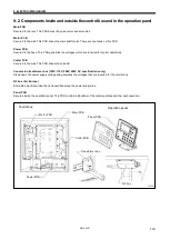
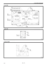
Страница 123: ...control operations Cutter PCB Secured to the side This PCB drives the solenoid Conversion transformer box 100V 110V 380V 400V AC specifications only Steps down the power supply voltage and generates the voltages that are required for the control box NF box For Europe Eliminates electrical noise that is transmitted along the power supply line Panel PCB Secured inside the operation panel This PCB co...

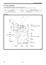
Страница 124: ...fied ones listed below If a component on a PCB is damaged the fuses may blow again soon even after they have been replaced No Part name Part code When a fuse has blown F1 F2 G Fuse 10A 250V glass tube fuse 10A 250V J04417 001 The power indicator is not illuminated and nothing operates Motor PCB 2930B ...

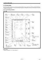
Страница 125: ...ding improper connection or sufficient contact Therefore be sure to check if each connector is correctly inserted and that there is no contact failure between pins and wires before starting troubleshooting procedures 9 4 1 Connector positions Main PCB Motor PCB Refer to the diagram in 9 3 Fuse explanation 0830D ...

Страница 126: ...9 ELECTRIC MECHANISM HE 800B 117 Power PCB Cutter PCB LCD panel PCB 0831D 0768D 0769D ...

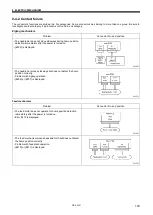
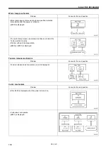
Страница 127: ...ion detection immediately after the power is turned on E200 is displayed The needle bar moves sideways but does not detect the home position correctly Problem with zigzag operation E200 or E201 is displayed Feed mechanism Problem Connector No and position The feed motor does not operate for home position detection immediately after the power is turned on Error E210 is displayed The feed mechanism ...

Страница 128: ...amp moves up and down but does not detect the home position correctly Problem with work clamp operation E300 or E301 is displayed Tension release mechanism Problem Connector No and position Tension release does not operate no error displayed Cutter mechanism Problem Connector No and position Error E650 is displayed when the power is turned on Cutter does not operate E651 is displayed 0838D 0839D 0...

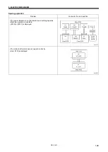
Страница 129: ...peration Problem Connector No and position The power indicator is not illuminated and nothing operates Machine operation is unstable E130 or E131 is displayed The main shaft motor does not operate correctly Error E130 is displayed 0841D 0842D ...

Страница 130: ... operation panel key does not have any effect The sewing machine does not operate when the foot switch is depressed No error display After the power is turned on E015 or E016 is displayed Error E055 is displayed after the power is turned on Error E452 is displayed after the power is turned on Continued on next page 0843D 0844D 0845D 2944B 2945B ...

Страница 131: ...isplay does not disappear and the sewing machine does not start Only the power indicator illuminates Nothing appears on the operation panel display The sewing machine does not operate when the foot switch is depressed Error E130 is displayed Error E131 is displayed 0848D 0849D 2948B 2949B ...

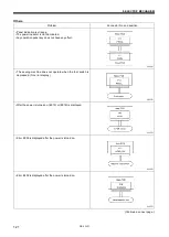
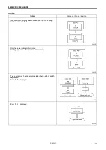
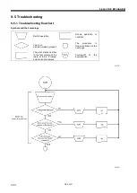
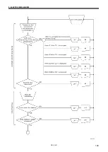
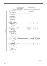
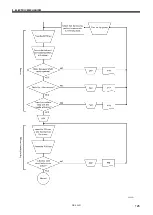
Страница 132: ...s and their meanings Switch operation Set up operation or condition Yes or no decision making process The procedure to follow continues on the next page The error status number in the first column of the table of 9 5 2 Problem solution and measures Turning off of the power switch 2707B 0850D ...

Страница 133: ...9 ELECTRIC MECHANISM HE 800B 124 0851D ...

Страница 134: ...9 ELECTRIC MECHANISM HE 800B 125 0852D ...

Страница 135: ...9 ELECTRIC MECHANISM HE 800B 126 0853D ...

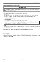
Страница 136: ...ing anything with a possibility of touching something inside the control box Injury When separating or rejoining connectors and measuring something be careful not to cut your fingers on metal parts such as heat sinks and covers 2 When replacing a fuse be sure to use a new one of the same quality and capacity as the old one Before adjustment 1 While the power is turned off check each connector is s...

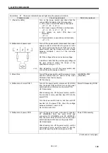
Страница 137: ...ing turn off the power switch and connect the power supply connector 3 Blown fuse Turn off the power switch wait 5 minutes or more and then remove fuses F1 and F2 on the motor PCB and check their continuity OK if continuity GFUSE10A 250V 10A 250V 4 Malfunction of motor PCB 1 Turn off the power switch disconnect P2 DCIN from the power PCB and then turn on the power switch and check LD2 red on the m...

Страница 138: ...ated After checking turn off the power switch wait for one minute or more and then insert P1 into the main PCB and P1 P2 and P3 into the motor PCB Main PCB assembly 800B 8 Malfunction of panel PCB Turn off the power switch disconnect connector P1 POWER2 from the main PCB and connectors P1 MT ENC and P2 MAIN from the motor PCB and then turn on the power switch and check LD2 red on the power PCB OK ...

Страница 139: ...nnector P14 HEAD SW is connected to the main PCB Switch assembly machine head 4 If E065 is displayed one of the keys on the operation panel is still depressed a Check that there is no incorrect sensitivity when the surface of the panel sheet and the keys are pressed b Check that connector P3 PANEL is connected to the motor PCB and that connector P1 MAIN is connected to the panel PCB Operation pane...

Страница 140: ...s abnormally high a Check that the power supply voltage at the mains is at the specification voltage plus or minus 10 b See 1 2 10 If E705 is displayed the power supply voltage is abnormally low a Check that the power supply voltage at the mains is at the specification voltage plus or minus 10 b See 1 2 Error status 3 Depress the treadle is not displayed when the power switch is turned on Probable...

Страница 141: ...ackward Foot switch 3 Malfunction of foot switch and cord option Check that the power is turned off Disconnect the foot switch from the foot switch adapter harness and measure the voltage between pins 5 6 and 7 8 of the foot switch connector Check between pins 9 10 if using a 3 pedal foot switch OK if the resistance is normally ohms but 0 ohms when depressed Foot switch 4 Malfunction of foot switc...

Страница 142: ...lown fuse a Remove fuses F1 and F2 from the motor PCB and check the continuity OK if there is continuity b If fuses F1 and F2 are blown check the resistances between each of the pins of the relay connector between the upper shaft motor and the motor PCB and between the terminals of the fuses OK if Ω c If the fuses blow again after they are replaced replace the motor PCB GFUSE10A 250V 10A 250V Moto...

Страница 143: ...1 and 2 3 and 4 of P21 OK if ohms c Insert P21 and P24 into the main PCB turn on the power switch and then check LD1 red on the power PCB OK if illuminated If LD1 is illuminated during the check in step 1 but it does not illuminate when P1 and P24 are connected there is a malfunction of the main PCB d Check LD1 orange on the main PCB OK if illuminated Main PCB assembly 800B 3 If zigzagging occurs ...

Страница 144: ...1 and 2 3 and 4 of P22 OK if ohms c Insert P22 and P24 into the main PCB turn on the power switch and then check LD1 red on the power PCB OK if illuminated If LD1 is illuminated during the check in step 1 but it does not illuminate when P1 and P24 are connected there is a malfunction of the main PCB d Check LD1 orange on the main PCB OK if illuminated Main PCB assembly 800B 3 If feeding occurs sli...

Страница 145: ...nd 2 3 and 4 of P23 OK if ohms c Insert P23 and P24 into the main PCB turn on the power switch and then check LD1 red on the power PCB OK if illuminated If LD1 is illuminated during the check in step 1 but it does not illuminate when P1 and P24 are connected there is a malfunction of the main PCB d Check LD1 orange on the main PCB OK if illuminated Main PCB assembly 800B 3 If the work clamp pulse ...

Страница 146: ...button clamp is touching anything 2 Incorrect mechanism adjustment Check if the work clamp mechanism upper thread trimming mechanism and lower thread trimming mechanism are moving stiffly Error status 11 The THREAD indicator does not illuminate during threading mode Probable causes Check repair adjust Parts to be replaced Malfunction of panel PCB Check that connector P3 PANEL is connected to the m...

Страница 147: ...on release solenoid Disconnect main PCB connector P3 SOL2 and measure the resistance between pins 1 2 of the cord connector OK if 6 8 ohms Tension release solenoid 3 Malfunction of main PCB a Turn on the power switch and check LD2 green on the main PCB OK if illuminated b With connector P3 SOL2 disconnected from the main PCB check the continuity between terminals 1 and 2 of connector P3 on the mai...

Страница 148: ...ose to any equipment that generates strong electrical interference 4 If E111 E130 E131 E132 or E133 is displayed after the sewing machine operates there is a malfunction of the motor PCB Refer to steps 1 to 4 in 5 Resolver stator assembly Motor PCB assembly 800B 5 If error E111 E130 E132 or E133 is displayed after the sewing machine operates there is a malfunction of the motor PCB or of the upper ...

Страница 149: ...measure the resistances between pins 1 and 3 and pins 2 and 4 of the cord side connector OK if 6Ω to 8Ω between 1 and 3 and 13Ω to 15Ω between 2 and 4 Cutter solenoid assembly 3 Malfunction of cutter PCB a Turn off the power switch disconnect connector P2 SOL from the cutter PCB and then check the continuity between terminals 1 and 3 and terminals 2 and 4 of connector P2 on the cutter PCB OK if Ω ...

Страница 150: ...9 SD card read write mode cannot be activated Probable causes Check repair adjust Parts to be replaced 1 If error E422 or E425 is displayed the SD card is inserted incorrectly a Check the direction of insertion of the SD card Insert the card so that it matches the direction of the pattern on the card cover b Check the insertion of the SD card 2 If E424 is displayed the SD card is incorrectly forma...

Страница 151: ...n the power was turned on or there is a problem with the stop switch connection Turn off the power and check the connection of the stop switch connector P9 at the main P C board E016 Problem with the stop switch connection Turn off the power and check the connection of the stop switch connector P9 at the main P C board E025 Treadle was still depressed to the 2nd step when the power was turned on o...

Страница 152: ...ne could not stop correctly at the needle up stop position after sewing Turn off the power and then check that there are no problems with the cutter mechanism the thread trimming mechanism and the upper shaft motor mechanism E112 The needle bar dropped during home position detection or while the SD card was being accessed Turn off the power and then turn it back on again If this error occurs when ...

Страница 153: ...main P C board are properly connected E201 Needle zigzag motor stopped due to a problem Turn off the power and then check if there are any problems in the needle zigzag direction E210 Feed motor home position cannot be detected Feed motor feed sensor or feed encoder signal is not connected correctly Turn off the power and then check that the feed sensor connector P8 feed encoder connector P18 and ...

Страница 154: ...ar the error Check the data on the SD card E424 Insufficient free space on the SD card Press the RESET key to clear the error Use a different SD card E425 An error occurred while writing to the SD card Press the RESET key to clear the error Check if the media is write protected and if it has enough free space E430 Problem with flash memory on main P C board Turn the power off and then back on agai...

Страница 155: ... home position Cutter is lowered Turn off the power and then check if there are any problems with the cutter mechanism Check that cutter solenoid connector P2 on the cutter P C board is properly connected E651 Cutter has not operated Does not drop Turn off the power and then check that cutter sensor connector P7 on the main P C board and cutter solenoid connector P2 on the cutter P C board are pro...

Страница 156: ...ed into the correct folder E884 There is a problem with the control program Write the correct file onto the SD card E885 Writing of the control program cannot begin Turn off the power and then check that there are no problems with the wiring and the P C boards inside the control box which are to have their firmware versions updated E886 Data error occurred during writing of the control program Tur...

Страница 157: ...hat fits the thread Threading Upper thread threading Thread the upper thread correctly INSTRUCTION MANUALCD Lower thread threading Thread the lower thread correctly INSTRUCTION MANUALCD Thread path Flaw or abrasion on the thread path Polish with buff or replace the part Especially pay attention to finishing around needle plate hole Flaw on the rotary hook tip and rotary hook edge Polish with buff ...

Страница 158: ... inner and rotary hook Upper thread amount Arm thread guide position Adjust the arm thread guide position INSTRUCTION MANUALCD Bobbin case Damaged outside of bobbin case and bent bobbin holder spring etc Polish with buff or replace the part Use the HE 800B bobbin case 11 2 Skipped stitches Items with a in the Page column should only be handled by a qualified technician Cause Check Remedy Page Need...

Страница 159: ...the left and right with your finger and check that the tip of the rotary hook does not strike the needle 91 Thread tension Zigzag thread upper thread tension Adjust the upper thread tension appropriately INSTRUCTION MANUALCD Needle bar play Vertical and longitudinal needle bar play Reduce the needle bar play or replace the parts Lower thread clamp Lower thread retainer cam Lower thread retainer ca...

Страница 160: ...e thread take up amount so that upper thread does not pull out of trimmer assembly at the sewing start 109 Lower thread bobbin slip Lower thread tension Adjust the lower thread tension appropriately INSTRUCTION MANUALCD Bobbin holder spring Add tension to the bobbin holder spring Lower thread retainer position Adjust the lower thread retainer position Adjust lower thread retainer so that a 35 40 m...

Страница 161: ... are bent replace them Check that the screws are tightened 11 5 Uneven seams 3 Seam lifts up at the sewing start Seam lifts up and does not tighten at the sewing start Items with a in the Page column should only be handled by a qualified technician Cause Check Remedy Page Upper thread trimmer Upper thread trimmer gradual opening timing Adjust the timing so that the upper thread trimmer gradually s...

Страница 162: ...MANUALCD Stitch patterns Purl stitch whip stitch Set using parameter number 53 INSTRUCTION MANUALCD Tension release Tension release timing Use parameter numbers 54 to 57 to set the timing for changing the thread tension INSTRUCTION MANUALCD 11 8 Uneven seams 6 Around rear tack or front tack Items with a in the Page column should only be handled by a qualified technician Cause Check Remedy Page Ten...

Страница 163: ...face of the opening cam 101 Lower thread clamp opening timing Adjust so that the lower thread clamp plate opens when the feed mechanism moves 6 7 mm 105 11 11 Uneven seams 9 Sticking in needle plate Front and rear tack sections of material gets stuck in needle hole Items with a in the Page column should only be handled by a qualified technician Cause Check Remedy Page Start backtack Number of star...

Страница 164: ...le Replace needle with one that fits for the thread Rotary hook holder Flaw on the rotary hook holder Polish with buff or replace the part 91 Rotary hook holder and inner rotary hook overlap amount Adjust the rotary hook holder and inner rotary hook overlap amount 91 Rotary hook Rotary hook lubrication Decrease the quantity of lubrication oil Note that if you reduce the amount of oil too much thre...

Страница 165: ...djustment Upper thread trimmer cutting depth adjustment 98 99 Upper thread trimmer assembly holding force Adjust so that the thread does not come out when you cut it with trimmer and hold the end of the thread between your fingers and gently swing the assembly Bend the trimmer U or replace them so that the correct force is applied Repair any damage from striking the needle Opening cam position Adj...

Страница 166: ...amount The gauge is an option part 1 Adjust the needle bar height to 1 on the gauge 2 Adjust the needle and rotary hook timing to 2 on the gauge 88 89 Thread chips on rotary hook edge Remove thread chips Lower thread Lower thread retaining amount Adjust the lower thread retaining amount 104 Lower thread snapping Adjust the positions of the lower thread retainer lower thread clamp and lower thread ...

Страница 167: ...ongitudinal position adjustment Upper thread trimmer cutting depth adjustment 98 99 Burr on tips of upper thread trimmer M and upper thread trimmer U Polish with buff or replace the part Tension release timing Opening amount of zigzag tension discs and bar tack tension discs particularly zigzag tension discs Adjust the zigzag tension discs by moving the tension stud bracket in and out Adjust the b...

Страница 168: ... trimmer longitudinal position adjustment Upper thread trimmer cutting depth adjustment 98 99 Upper thread trimmer assembly holding force Adjust so that the thread does not come out when you cut it with trimmer and hold the end of the thread between your fingers and gently swing the assembly Bend the trimmer U or replace them so that the correct force is applied Repair any damage from striking the...

Страница 169: ...the upper thread trimmer driving link so that it stops at the face plate In this position tighten the bolts so that the small slot in the upper thread trimmer lever and the edge of the washer are aligned 97 Cam Upper thread trimmer opening timing Adjust so that the cam opens the stop plate properly 102 Opening cam Upper thread trimmer gradual opening timing Adjust the timing so that the upper thre...

Страница 170: ...ook Adjust the gap between the needle and the rotary hook tip to 0 01 0 08 mm Adjust to as large as possible without causing skipped stitches to occur Move the needle bar to the left and right with your finger and check that the tip of the rotary hook does not strike the needle 91 Needle plate Needle plate position Adjust the forward back position of the needle plate so that the needle is in the c...

Страница 171: ...enoid connector P2 on the cutter P C board are properly connected INSTRUCTION MANUALCD Solenoid stopper Nut Check if the nut is loose and tighten it securely Cutter sensor position Adjust the cutter sensor position Check if the mounting screws are loose and tighten them securely 66 Cutter bar guide Smoothness of cutter operation Adjust the cutter bar guide so that the cutter operates smoothly with...

Страница 172: ...e column should only be handled by a qualified technician Cause Check Remedy Page Setting the length of the hole Length of the hole Set parameter number 02 to the same value as the length of the cutter being used INSTRUCTION MANUALCD Setting the cutter spacing Cutting of zigzag seam Use parameter number 04 to set the cutter X space Use parameter number 03 to set the correction of the cutter X posi...

Страница 173: ...ease work clamp pressure Press material so that the material is properly stretched When using knits or woven materials replace the parts with the 3 specification parts Length feed plate for specification 3 work clamp assembly for knits needle plate 1 2 for specification 3 Underlay Underlay is being sewn Use parameter number 47 to reduce the underlay feed pitch to about 0 5 Use parameter number 14 ...

Страница 174: ... setting Change the settings of memory switch Nos 001 002 003 004 If the work clamp lifting height is too high the lower thread trimming operation and the work clamp lifting will become stiff and the work clamp motor may go out of step INSTRUCTION MANUALCD Threading Lower thread threading Insert the bobbin correctly and pass the lower thread through the bobbin case correctly If the bobbin is inser...

Страница 175: ... if there are any problems with the connection and contacts of feed motor connector P22 on the main P C board INSTRUCTION MANUALCD Upper thread trimmer Upper thread trimmer position Remove and re install the upper thread trimmer 101 Check if the cam opens the stop plate Adjust the cam position If the feed mechanism operates when the cam has not opened the stop plate the cutter will bump against th...

Страница 176: ...t to obtain the optimum stitches INSTRUCTION MANUALCD 11 29 Upper shaft does not rotate as far as the needle up stop position Items with a in the Page column should only be handled by a qualified technician Cause Check Remedy Page Thread retainer and rotary hook are touching Thread trimmer mechanism position 1 Turn the machine pulley backward to set the needle bar to the needle up position 2 Push ...

Страница 177: ...MEMO 168 HE 800B ...

Страница 178: ...SERVICE MANUAL 2014 Brother Industries Ltd All Rights Reserved HE 800B I3061003D 2014 03 D 1 ...

Отзывы: