


III
- 8
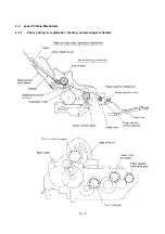
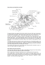
(3) Developing process
The developing process develops an electrostatic latent image formed on the drum in the
exposing process, into a toner image.
The developer roller attracts the toner particles fed from the toner cartridge by the toner supply
roller, and then conveys them to the contact section with the laser-sensitive drum
On the contact section between the developer roller and drum, the positive toner particles stick to
the neutralized spots on the drum according to the principles of attraction and repulsion,
transforming a latent image into a toner image.
The toner augers (which agitate toner particles in the chamber) and the blade allow toner particles
to be fed onto the developer roller at an even thickness.
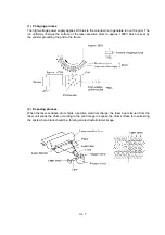
(4) Transferring process
When a paper passes between the drum and the transfer roller, the switch "a" (see the above
illustration) is turned on to negatively charge the transfer roller. The toner is positive, so the toner
image formed on the drum will be transferred onto the paper according to the same principle as for
the developing process.
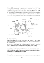
If the toner image fails to stick to the paper due to paper jam or other errors, it will stick to the
transfer roller. To repulse this toner, the switch "b" (see the above illustration) is turned on to
positively charge the transfer roller. The toner returns from the transfer roller to the drum.
Cleaning the drum
In the transferring process, not all the toner particles on the drum are transferred onto the paper
but some toner particles remain on the drum. The cleaner roller cleans the drum surface and
collects the residual toner. When printing starts or during non-printing, the toner collected on the
cleaner roller will be discharged onto the drum and returned to the chamber through the developer
roller for recycling in the subsequent developing process.
(5) Erasing process
The eraser lamp emits light to expose the drum surface, which erases the residual electrical
charge.
Содержание FAX-8650P
Страница 1: ...FACSIMILE EQUIPMENT SERVICE MANUAL MODEL FAX3750 FAX 8650P MFC7750 ...
Страница 5: ...CHAPTER I GENERAL DESCRIPTION ...
Страница 12: ...CHAPTER II INSTALLATION ...
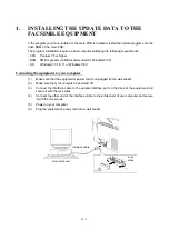
Страница 13: ...CONTENTS 1 INSTALLING THE UPDATE DATA TO THE FACSIMILE EQUIPMENT II 1 ...
Страница 16: ...CHAPTER III THEORY OF OPERATION ...
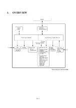
Страница 18: ...III 1 1 OVERVIEW Not provided on the FAX 8650P ...
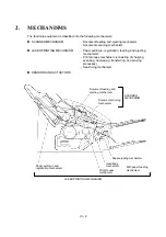
Страница 21: ...III 4 2 2 Laser Printing Mechanism 2 2 1 Paper pulling in registration feeding and ejecting mechanism ...
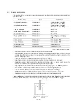
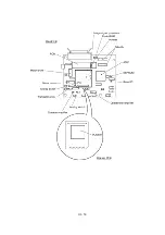
Страница 28: ...III 11 Not provided on the FAX 8650P Location of Sensors and Actuators ...
Страница 31: ...III 14 Main PCB Modem PCB ...
Страница 36: ...CHAPTER IV DISASSEMBLY REASSEMBLY AND LUBRICATION ...
Страница 42: ...IV 4 n n Disassembly Order Flow ...
Страница 71: ...IV 33 1 Provided on the FAX 8650P 2 Not provided on the FAX 8650P ...
Страница 72: ...IV 34 Setting up the main PCB after replacement ...
Страница 84: ...IV 46 2 Control panel locks 3 Scanner frame ASSY and separation roller gear ...
Страница 85: ...IV 47 4 Top cover lock spring 5 Gear drive unit ...
Страница 86: ...CHAPTER V MAINTENANCE MODE ...
Страница 93: ...V 6 Scanning Compensation Data List ...
Страница 141: ...V 54 FAX3750 FAX 8650P MFC7750 Key Button Entry Order ...
Страница 146: ...CHAPTER VI ERROR INDICATION AND TROUBLESHOOTING ...
Страница 171: ...Oct 98 SM5X5303 Printed in Japan ...
Страница 172: ...FAX3750 FAX 8650P MFC7750 Appendix 1 EEPROM Customizing Codes ...
Страница 194: ......
Страница 195: ......
Страница 196: ......


