


7-1
Confidential
1.
MAINTENANCE MODE
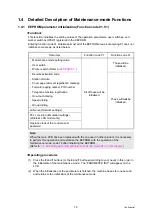
The maintenance mode is exclusively designed for the checking, setting and adjustments of
the machine by using the buttons on the control panel cover ASSY. The EEPROM can be
customized according to the destination of the machine. Moreover, the operational check of
the LCD, operation panel board, and sensors, print test, display of the log information and
error codes, and change of the worker switches (WSW) can be performed.
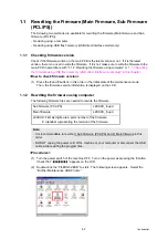
1.1 How to Enter the Maintenance Mode
<Operating procedure>
(1) Press the
Menu
button and then the
Start/Black
button while the machine is in the ready
state. Next, press the
button four times to enter the maintenance mode.
(2) The machine beeps for one second and displays “
” on the LCD,
indicating that it is placed in the initial state of the maintenance mode, a mode in which the
machine is ready to accept entry from the buttons.
(3) To select any of the maintenance mode functions shown in the next page, enter the
maintenance mode that you want to use using the buttons.
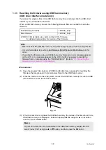
1.2
How to Enter the End User-accessible Maintenance Mode
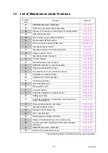
Basically, the maintenance-mode functions listed in the
should be accessed by
service personnel only. However, you can allow end users to access some of these under the
guidance of service personnel by phone, for example.
The end user-accessible functions are
shaded
in the table given on the
09, 10, 11, 12, 25, 43, 52, 53, 54, 68, 71, 72, 77, 80, 82, 87, 88
Function code 10 accesses the firmware switches, each of which has eight selectors. You
should not allow end users to access all of those selectors, but you can allow them to access
user-accessible selectors which are shaded in the firmware switch tables in
The service personnel should instruct end users to follow the procedure given below.
<Operating procedure>
(1) Press the
Menu
,
Start/Black
,
Menu
and
buttons in this order when the machine is in
the ready state. “MAINTENANCE 06” appears on the LCD.
(2) Press the
or
button to display the desired maintenance code on the LCD. Then
press the
OK
button.
To switch the machine back to the ready state, press the
Stop/Exit
button. When each of the
user-accessible functions is completed, the machine automatically returns to the ready state.
Memo:
FAX models equipped with numerical keypads can enter the maintenance mode in the
same way as conventional models; that is, by pressing the
Menu
,
*
,
2
,
8
,
6
and
4
buttons in this sequence.
Memo:
- To exit from the maintenance mode and switch to ready state, press the
9
button twice in
the initial state of the maintenance mode.
- When the
Stop/Exit
button is pressed, the machine beeps for one second and returns to
the initial state of the maintenance mode.
- When an incorrect maintenance mode is entered, the machine beeps for one second and
returns to the initial state of the maintenance mode.
Содержание DCP-9010CN
Страница 11: ...Confidential CHAPTER 1 SPECIFICATIONS ...
Страница 53: ...Confidential CHAPTER 2 THEORY OF OPERATION ...
Страница 90: ...Confidential CHAPTER 3 ERROR INDICATION AND TROUBLESHOOTING ...
Страница 201: ...Confidential CHAPTER 4 PERIODICAL MAINTENANCE ...
Страница 224: ...Confidential CHAPTER 5 DISASSEMBLY AND ASSEMBLY ...
Страница 440: ...Confidential CHAPTER 6 ADJUSTMENTS AND UPDATING OF SETTINGS REQUIRED AFTER PARTS REPLACEMENT ...
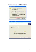
Страница 446: ...6 5 Confidential 10 Alert warning message appears click Continue Anyway to proceed ...
Страница 456: ...Confidential CHAPTER 7 SERVICE FUNCTIONS ...
Страница 464: ...7 6 Confidential For color scanning Fig 7 2 ...
Страница 487: ...7 29 Confidential Cover page sample Fig 7 13 End page sample Fig 7 14 ...
Страница 492: ...7 34 Confidential Color registration adjustment chart Fig 7 16 ...
Страница 496: ...7 38 Confidential LED test pattern M68_L Fig 7 18 ...
Страница 498: ...7 40 Confidential Fig 7 19 ...
Страница 500: ...7 42 Confidential Color test pattern Fig 7 20 MCYK Y C K M YCMK_ _A ...
Страница 518: ...Confidential CHAPTER 8 CIRCUIT DIAGRAMS WIRING DIAGRAM ...
Страница 520: ...Confidential 8 1 1 CIRCUIT DIAGRAMS High voltage Power Supply PCB Circuit Diagram SYS HITEK SPH 8N35 1 3 ...
Страница 521: ...Confidential 8 2 High voltage Power Supply PCB Circuit Diagram SYS HITEK SPH 8N35 2 3 ...
Страница 522: ...Confidential 8 3 High voltage Power Supply PCB Circuit Diagram SYS HITEK SPH 8N35 3 3 ...
Страница 523: ...Confidential 8 4 High voltage Power Supply PCB Circuit Diagram MURATA MPH3316 1 3 ...
Страница 524: ...Confidential 8 5 High voltage Power Supply PCB Circuit Diagram MURATA MPH3316 2 3 ...
Страница 525: ...Confidential 8 6 High voltage Power Supply PCB Circuit Diagram MURATA MPH3316 3 3 ...
Страница 526: ...Confidential 8 7 Low voltage Power Supply PCB Circuit Diagram 100V ...
Страница 527: ...Confidential 8 8 Low voltage Power Supply PCB Circuit Diagram 200V ...
Страница 528: ...Confidential 8 9 NCU PCB Circuit Diagram USA Canada ...
Страница 529: ...Confidential 8 10 NCU PCB Circuit Diagram Europe Asia Oceania China ...
Страница 530: ...Confidential 8 11 NCU PCB Circuit Diagram South Africa Gulf ...
Страница 531: ...Confidential 8 12 2 WIRING DIAGRAM Wiring Diagram 1 2 ...
Страница 532: ...Confidential 8 13 Wiring Diagram 2 2 ...
Страница 590: ...Confidential APPENDIX 3 SERIAL NUMBERING SYSTEM ...
Страница 592: ...App 3 2 Confidential Serial number of the LED ASSY Print position Fig App 3 4 Serial number ...
Страница 593: ...Confidential APPENDIX 4 SCREW CATALOGUE ...
Страница 595: ...Confidential APPENDIX 5 REFERENCES ...
Страница 597: ...Confidential APPENDIX 6 GLOSSARY ...


