


App. 1-33
Confidential
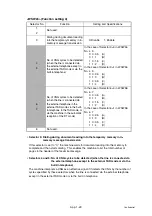
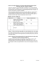
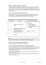
<WSW31> (Function setting 9)
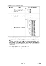
• Selector 2: Default reduction rate for failure of automatic reduction during recording
This selector sets the default reduction rate to be applied if the automatic reduction function
fails to record one-page data sent from the calling station in a single page of the current
recording paper.
If it is set to "0," the machine records one-page data at full size (100%) without reduction; if
it is set to "1," the machine records it at 70% size.
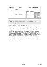
• Selector 5: Minimum ON and OFF duration of ringer signals effective in distinctive
ringing
The ringer pattern consists of short and long rings, e.g., short-short-long rings. This
selector sets the minimum ON and OFF duration of ringer signals that are required for the
machine to interpret ringer signals as being ON or OFF. This is to prevent components of
a ringer pattern from being misinterpreted due to chattering in distinctive ringing.
The machine monitors ringer signals at 10-ms intervals. If the signal is ON, the machine
1; if it is OFF, it counts -1. If the counter increments up to +5 or +13 when this
selector is set to "1" (90 ms) or "0" (130 ms), respectively, the machine interprets the
current signal as being ON.
If the counter returns to zero, the machine interprets the signal as being OFF.
If the Distinctive Ring is set to OFF, this selector is not effective.
Selector No.
Function
Setting and Specifications
1
Not used.
2
Default reduction rate for failure
of automatic reduction during
recording
0: 100 %
1: 75 %
3
Not used.
4
(Do not disturb this selector.)
5
Minimum ON and OFF duration
of ringer signals effective in
distinctive ringing
0: 130 ms
1: 90 ms
6
I
7
Not used.
8
Drum life indication
0: No
1: Yes
Note:
• Selector 5 is applicable only to the U.S.A. models.
Содержание DCP 8085DN
Страница 13: ...CHAPTER 1 SPECIFICATIONS ...
Страница 52: ...Confidential CHAPTER 2 THEORY OF OPERATION ...
Страница 69: ...2 16 Confidential 3 3 Paper Feeding Fig 2 18 LT path DX path MP path Paper tray path ...
Страница 89: ...CHAPTER 3 ERROR INDICATION AND TROUBLESHOOTING ...
Страница 178: ...Confidential CHAPTER 4 PERIODICAL MAINTENANCE ...
Страница 204: ...4 25 Confidential 23 Secure the Fuser unit with the pan B M4x20 Taptite screw Fig 4 37 Taptite pan B M4x20 Fuser unit ...
Страница 248: ...CHAPTER 5 DISASSEMBLY REASSEMBLY ...
Страница 265: ...5 12 Confidential Fig 5 7 EM2 4 places Separation pad ASSY ...
Страница 291: ...5 38 Confidential 38 Driver PCB Battery CIS model Main PCB Battery harness Drive PCB Battery Driver harness ...
Страница 400: ...5 147 Confidential 9 11 3 Printed Rubber Key 1 Remove the Printed rubber key Fig 5 170 Printed rubber key Panel cover ...
Страница 452: ...5 199 Confidential 9 33 Thermistor ASSY 1 Remove the Thermistor ASSY from the Frame L Fig 5 242 Frame L Thermistor ASSY ...
Страница 501: ...Confidential CHAPTER 6 ADJUSTMENTS AND UPDATING OF SETTINGS REQUIRED AFTER PARTS REPLACEMENT ...
Страница 507: ...6 5 Confidential 8 Alert warning message of WHQL appears Click Continue Anyway to proceed ...
Страница 516: ...CHAPTER 7 SERVICE MODE ...
Страница 525: ...7 7 Confidential For color scanning Fig 7 2 ...
Страница 527: ...7 9 Confidential For white and black scanning Fig 7 3 ...
Страница 528: ...7 10 Confidential For color scanning Fig 7 4 ...
Страница 567: ...Confidential CHAPTER 8 CIRCUIT DIAGRAMS WIRING DIAGRAM ...
Страница 569: ...8 1 Confidential 1 CIRCUIT DIAGRAMS High voltage Power Supply PCB Circuit Diagram Fig 8 1 ...
Страница 570: ...8 2 Confidential LVPS PCB Circuit Diagram 230V Fig 8 2 ...
Страница 571: ...8 3 Confidential LVPS PCB Circuit Diagram 115V Fig 8 3 ...


