


4-2
Confidential
1.1
Periodical Maintenance Parts
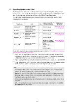
Periodical maintenance parts are the parts to be replaced periodically to maintain product
quality. These parts would affect the product quality greatly if they lost their function even if
they do not appear to be damaged or there is no change in their appearance.
The periodical maintenance parts listed below should be replaced at the service center
referring to the service life.
To reset the count of each periodical maintenance parts, refer to
Maintenance Parts Life" in Chapter7
*1
At 5% print coverage (A4 or Letter size). The actual number of printed pages will vary
depending on the print jobs and paper you use. The number is calculated when simplex
printed the normal business document (ISO/IEC19752) on the A4 size.
*2
Paper feeding kit MP means the MP roller holder ASSY and the separation pad ASSY MP.
*3
Paper feeding kit for Tray 1 and Tray 2 means the roller holder ASSY, the separation pad
ASSY and the separation pad spring. Tray 1 and Tray 2 are the same kit.
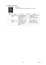
Parts Name
LCD
Qty
Approximate Life
*1
(number of prints)
Replacement
Procedure
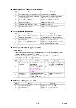
Fuser Unit
REPLACE PARTS
FUSER UNIT
1
100,000 pages
Laser Unit
REPLACE PARTS
LASER UNIT
1
100,000 pages
PF kit for Tray 1
*3
REPLACE PARTS
PF KIT1
1
100,000 pages
PF kit for Tray 2
*3
REPLACE PARTS
PF KIT2
1
100,000 pages
MP PF tray
*2
REPLACE PARTS
PF KIT MP
1
Except for China/
India: 50,000 pages
China:
25,000 pages
India:
12,000 pages
Note :
• Always turn off the power switch of the machine and unplug the power cord from the
power outlet before replacing the periodical maintenance parts.
• If the Fuser Unit is replaced after errors related to the Fuser Unit occur, it is necessary to
leave the machine power ON for 15 minutes after part replacement. This will make the
machine to be released from errors.
• After disconnecting flat cables, check that each cable is not damaged at its end or short-
circuited.
• When connecting flat cables, do not insert them at an angle. After insertion, check that
the cables are not at an angle.
Содержание DCP 8085DN
Страница 13: ...CHAPTER 1 SPECIFICATIONS ...
Страница 52: ...Confidential CHAPTER 2 THEORY OF OPERATION ...
Страница 69: ...2 16 Confidential 3 3 Paper Feeding Fig 2 18 LT path DX path MP path Paper tray path ...
Страница 89: ...CHAPTER 3 ERROR INDICATION AND TROUBLESHOOTING ...
Страница 178: ...Confidential CHAPTER 4 PERIODICAL MAINTENANCE ...
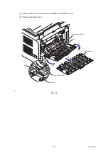
Страница 204: ...4 25 Confidential 23 Secure the Fuser unit with the pan B M4x20 Taptite screw Fig 4 37 Taptite pan B M4x20 Fuser unit ...
Страница 248: ...CHAPTER 5 DISASSEMBLY REASSEMBLY ...
Страница 265: ...5 12 Confidential Fig 5 7 EM2 4 places Separation pad ASSY ...
Страница 291: ...5 38 Confidential 38 Driver PCB Battery CIS model Main PCB Battery harness Drive PCB Battery Driver harness ...
Страница 400: ...5 147 Confidential 9 11 3 Printed Rubber Key 1 Remove the Printed rubber key Fig 5 170 Printed rubber key Panel cover ...
Страница 452: ...5 199 Confidential 9 33 Thermistor ASSY 1 Remove the Thermistor ASSY from the Frame L Fig 5 242 Frame L Thermistor ASSY ...
Страница 501: ...Confidential CHAPTER 6 ADJUSTMENTS AND UPDATING OF SETTINGS REQUIRED AFTER PARTS REPLACEMENT ...
Страница 507: ...6 5 Confidential 8 Alert warning message of WHQL appears Click Continue Anyway to proceed ...
Страница 516: ...CHAPTER 7 SERVICE MODE ...
Страница 525: ...7 7 Confidential For color scanning Fig 7 2 ...
Страница 527: ...7 9 Confidential For white and black scanning Fig 7 3 ...
Страница 528: ...7 10 Confidential For color scanning Fig 7 4 ...
Страница 567: ...Confidential CHAPTER 8 CIRCUIT DIAGRAMS WIRING DIAGRAM ...
Страница 569: ...8 1 Confidential 1 CIRCUIT DIAGRAMS High voltage Power Supply PCB Circuit Diagram Fig 8 1 ...
Страница 570: ...8 2 Confidential LVPS PCB Circuit Diagram 230V Fig 8 2 ...
Страница 571: ...8 3 Confidential LVPS PCB Circuit Diagram 115V Fig 8 3 ...


