5-3
Confidential
1.4
Detailed Description of Maintenance-mode Functions
1.4.1 EEPROM Parameter Initialization (Function code 01, 91)
<Function>
The machine initializes the parameter, user switches, worker switches and assurance mode
switch settings registered in the EEPROM, to the initial values. Entering function code 01
initializes almost all of the EEPROM areas, but entering 91 does not initialize some areas, as
listed below.
Note:
If you replace the main PCB with the one used for any other machine, carry out this
procedure and then customize the EEPROM
(maintenance-mode function code 74 in
<Operating Procedure>
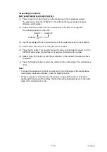
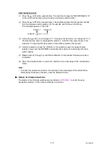
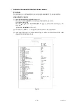
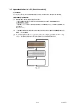
(1) MFC7840W/7840N/7450/7440N/7340/7320
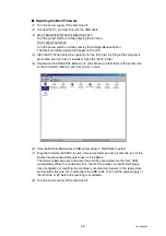
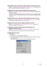
Press in order the 0 and 1 buttons (or the 9 and 1 buttons according to your need) in the
initial stage of the maintenance mode.
DCP7045N/7040/7030
Press the
or
button. "MAINTENANCE 01" or "MAINTENANCE 91" appears on the
LCD, and then press the OK button.
The "PARAMETER INIT" will appear on the LCD.
(2) Upon completion of parameter initialization, the machine beeps for one second and
returns to the initial stage of the maintenance mode.
Note:
When turn power supply of the machine off after upon completion of EEPROM
parameter initialization, turn off after waiting more than three seconds after returns to the
initial stage of the maintenance mode.
The LAN setting data might not be initialized.
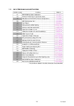
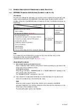
Function code
Data item
01
91
Maintenance-mode functions
User switches
Worker switch (Refer to
Remote activation code
Registered message for cover page comment
Forwarding / paging number, PIN number
Outside line number
Telephone function registration
One-touch dialing
Speed dialing
Group dialing
Various LAN setting (Only the model with network)
All of these will
be initialized.
These will be
initialized.
These will not
be initialized.
Содержание DCP-7030
Страница 78: ...2 2 Confidential 2 PERIODICAL PEPLACEMENT PARTS There are no parts to be replaced periodically ...
Страница 133: ...3 55 Confidential 8 12 8 ADDRESS LABEL 1 Remove the Address label from the Panel unit Fig 3 53 Address label Panel unit ...
Страница 150: ...3 72 Confidential 8 27 FILTER ASSY 1 Remove the Filter ASSY from the Main body Fig 3 72 Filter ASSY Front side ...
Страница 178: ...3 100 Confidential 8 39 RUBBER FOOT 1 Remove the two Rubber feet from the Main body Fig 3 104 Rubber foot Front side ...
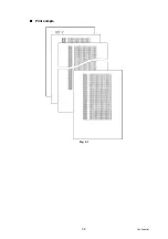
Страница 201: ...5 5 Confidential Print sample Fig 5 1 ...
Страница 226: ...5 30 Confidential Location of fans Fig 5 13 Fan motor 60 unit Right side ...
Страница 233: ...6 1 Confidential CHAPTER 6 CIRCUIT DIAGRAMS WIRING DIAGRAM High voltage Power Supply PCB Circuit Diagram ...
Страница 234: ...6 2 Confidential LVPS PCB Circuit Diagram 100V ...
Страница 235: ...6 3 Confidential LVPS PCB Circuit Diagram 200V ...
Страница 239: ...6 7 Confidential Wiring Diagram ...

