background image

3-20

Confidential

9.9

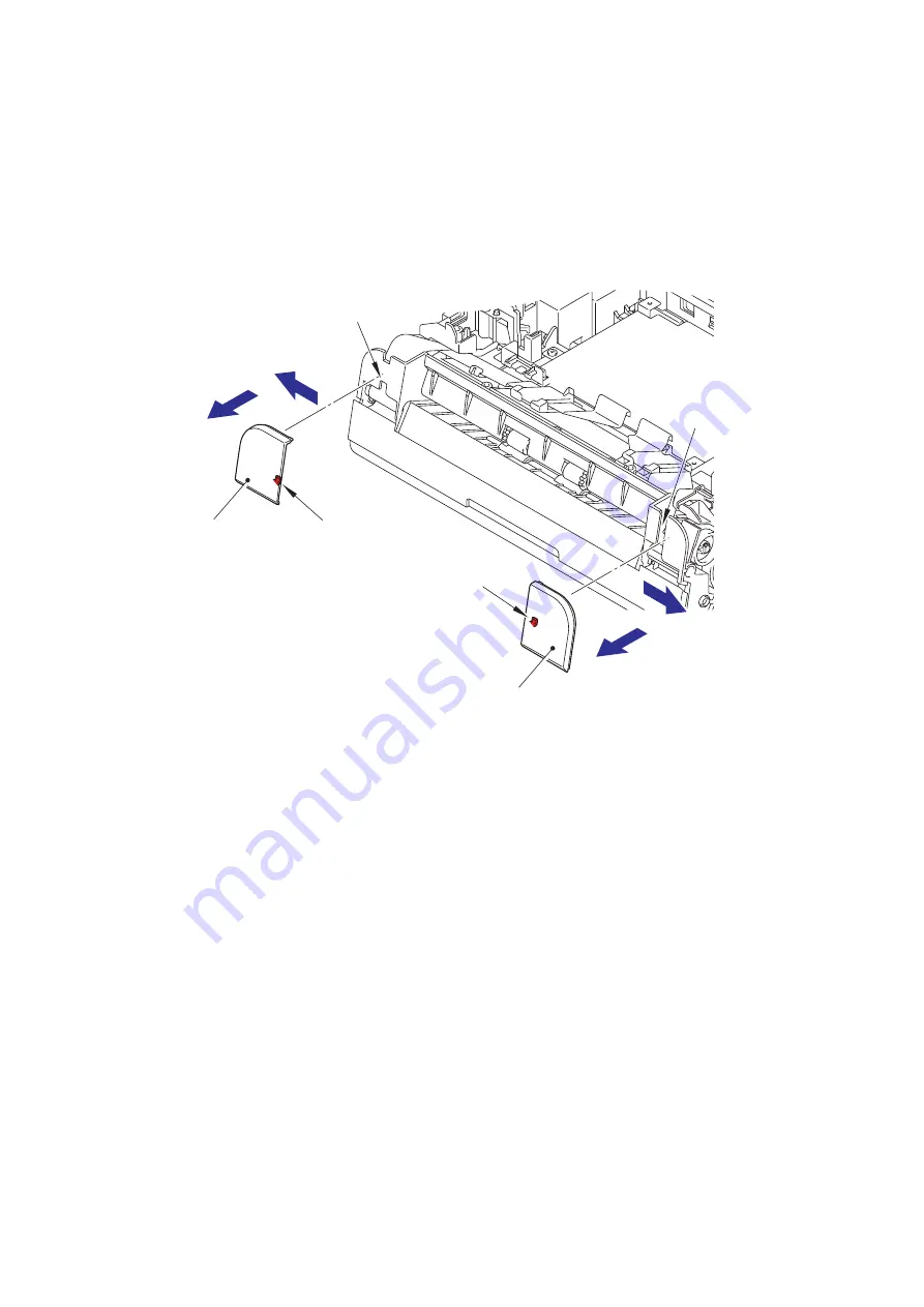
Front cover L/R

(1) Slide the front cover L in the direction of arrow 1a. Engage the rib on the front cover L with 

the notch on the machine to pull out and remove the front cover L from the machine in the 
direction of arrow 1b.

(2) Slide the front cover R in the direction of arrow 2a. Engage the rib on the front cover R with 

the notch on the machine to pull out and remove the front cover R from the machine in the 
direction of arrow 2b.

Fig. 3-15

Rib

Notch

Front cover R

Rib

Notch

Front cover L

2a

2b

1b

1a

Содержание ADS-2000e

Страница 1: ...other Advanced Document Scanner SERVICE MANUAL MODEL ADS 2000 2100 Read this manual thoroughly before maintenance work Keep this manual in a convenient place for quick and easy reference at all times Mar 2012 SM PT045 ...

Страница 2: ...tion may be reproduced in any form or by any means without permission in writing from the publisher All other product and company names mentioned in this manual are trademarks or registered trademarks of their respective holders Specifications are subject to change without notice ...

Страница 3: ...ck Memory Stick PRO Memory Stick PRO Duo Memory Stick Duo MagicGate Memory Stick Memory Stick Micro and M2 are trademarks of Sony Corporation AOSS is a trademark of Buffalo Inc Wi Fi WPA WPA2 Wi Fi Protected Access and Wi Fi Protected Setup are either trademarks or registered trademarks of Wi Fi Alliance in the United States and or other countries Intel and Pentium are trademarks of Intel Corporat...

Страница 4: ...n an Error Occurs 2 8 3 2 Status Error Messages 2 13 4 TROUBLESHOOTING 2 14 4 1 Troubleshooting for Error Display 2 14 4 1 1 The double feeding sensor detected multiple documents 2 14 4 1 2 The document scanning position sensor detected that the document length was 40 cm or more Document jam 2 14 4 1 3 The document scanning position sensor has not detected the top of the document even after the do...

Страница 5: ...t within the standard was scanned when the maintenance mode function Acquire white level data and set CIS scan area was executed A black level not within the standard was scanned when the maintenance mode function Acquire white level data and set CIS scan area was executed 2 16 4 2 Troubleshooting for Image Defects 2 17 4 2 1 Defect examples 2 17 4 2 2 Troubleshooting according to image defect 2 1...

Страница 6: ...Document scanning position actuator Double feeding sensor Sent Separation pad ASSY 3 24 9 13 Second side CIS unit 3 29 9 14 Top cover Document guide LS Document guide RS 3 30 9 15 Back cover S 3 31 9 16 Back cover 3 32 9 17 Power supply PCB ASSY 3 33 9 18 Main motor 3 36 9 19 Front cover sensor 3 37 9 20 Double feeding sensor PCB ASSY Receive 3 38 9 21 First side CIS unit 3 39 9 22 One way clutch ...

Страница 7: ...ration Pad Counters 4 12 CHAPTER 5 SERVICE FUNCTIONS 1 MAINTENANCE MODE 5 1 1 1 How to Enter Maintenance Mode 5 1 1 1 1 Method of entering end user accessible maintenance mode 5 1 1 1 2 Method of entering maintenance mode for service personnel 5 1 1 2 List of Maintenance Mode Functions 5 2 1 3 Details of Maintenance Mode Functions 5 3 1 3 1 Change USB No return value End user accessible maintenanc...

Страница 8: ...If you need to replace the plug fuse fit a fuse that is approved by ASTA to BS1362 with the same rating as the original fuse Always replace the fuse cover Never use a plug that does not have a cover If in any doubt call a qualified electrician Warning This product must be earthed The wires in the mains lead are coloured in line with the following code Green and Yellow Earth Blue Neutral Brown Live...

Страница 9: ...6 66 EC Directives The product battery is marked with one of the above recycling symbols It indicates that at the end of the life of the product battery you should dispose of it separately at an appropriate collection point and not place it in the normal domestic waste stream CAUTION DO NOT connect this product to a LAN connection that is subject to over voltages Product mark Battery mark European...

Страница 10: ...n accordance with the instructions may cause harmful interference to radio communications However there is no guarantee that interference will not occur in a particular installation If this equipment does cause harmful interference to radio or television reception which can be determined by turning the equipment off and on the user is encouraged to try to correct the interference by one or more of...

Страница 11: ...tilisation de ce dispositif est autorisée seulement aux conditions suivantes 1 il ne doit pas produire de brouillage et 2 l utilisateur du dispositif doit être prêt à accepter tout brouillage radioélectrique reçu même si ce brouillage est susceptible de compromettre le fonctionnement du dispositif For use in the USA or Canada only These products are made for use in the USA and Canada only We canno...

Страница 12: ...tes a potentially hazardous situation which if not avoided may result in damage to property or loss of product functionality Prohibition icons indicate actions that must not be performed Electrical Hazard icons alert you to possible electrical shock Fire Hazard icons alert you to the possibility of fire Hot Surface icons warn you not to touch product parts that are hot Note Notes tell you how you ...

Страница 13: ...uct including for routine maintenance such as cleaning make sure you have unplugged the power cord from the AC power outlet as well as Ethernet RJ 45 cables Network models only from the product Never push objects of any kind into this product through cabinet slots since they may touch dangerous voltage points or short out parts DO NOT handle the plug with wet hands DO NOT use this product during a...

Страница 14: ...eplace your obsolete outlet DO NOT defeat the purpose of the grounded plug Use only the power cord supplied with this product DO NOT allow anything to rest on the power cord DO NOT place this machine where people can walk on the cord DO NOT place this machine in a position where the cord is stretched or strain is otherwise put on the cord as it may become worn or fray Brother strongly recommends t...

Страница 15: ...Confidential CHAPTER 1 SPECIFICATIONS ...

Страница 16: ...s chapter lists the specifications of each model CONTENTS 1 SPECIFICATIONS LIST 1 1 1 1 General 1 1 1 2 Network Connectivity 1 3 1 3 Service Information 1 3 1 4 Paper 1 4 1 4 1 Paper handling 1 4 1 4 2 Media specifications 1 4 1 5 Scanner 1 5 ...

Страница 17: ...m 48 image per min 2 5 seconds A4 LTR CPU StarSapphire 400 MHz Memory 256 MB Interface USB Hi Speed 2 0 Power consumption Scanning Approximately 18 W Ready Approximately 7 W Deep Sleep Approximately 1 5 W Power Off Approximately 0 25 W Approximately 0 3 W for Chile Argentina Approximately 0 3 W Environment Temperature Operating 5 to 35 C Storage 0 to 40 C Humidity Operating 20 to 80 Storage 10 to ...

Страница 18: ...quivalent 128 MB 256 MB 150 MB 1 5 GB USB Windows Vista 2 Intel Pentium 4 or equivalent 64 bit Intel 64 or AMD 64 supported CPU 512 MB 1 GB 500 MB 1 5 GB Windows 7 2 1 GB 32 bit 2 GB 64 bit 1 GB 32 bit 2 GB 64 bit 650 MB 1 5 GB Macintosh Operating System OS X 10 5 8 PowerPC G4 G5 Intel Processor 512 MB 1 GB 80 MB 580 MB USB 1 OS X 10 6 x Intel Processor 1 GB 2 GB OS X 10 7 x Intel Processor 2 GB 2...

Страница 19: ...twork type N A Network security N A Wireless network Network node type N A Network type N A Communication mode N A Network security N A Part Approximate Life pages Machine life 100 000 sheets A4 LTR or 5 years 1000 times Plastic card scan MTBF 4 000 hours MTTR 0 5 hours Maximum monthly volume 10 000 sheets A4 LTR Periodical maintenance parts SeparationPad for ADF 50 000 sheets A4 LTR Separation Ro...

Страница 20: ...Input 50 sheets ADF Output 50 sheets Duplex Scan Yes Model ADS 2000 ADS 2100 Paper Input ADF Plain Paper Thin Paper Thick Paper Thicker Paper Recycled Paper Post Card JPN Business Card Plastic Card Media Weight ADF muptiple paper 52 to 110 g m2 ADF single paper 52 to 200 g m2 Media Size ADF muptiple paper Width 51 to 215 9 mm Length 70 to 297 0 mm ADF single paper Width 51 to 215 9 mm Length 70 to...

Страница 21: ... X 10 6 x 10 7 x 2 ISISTM Compliant Windows Windows XP 1 Windows Vista Windows 7 Color Depth Input 30 bit color Processing Output 24 bit color Processing Resolution Interpolated Up to 1200 x 1200 dpi Optical Up to 600 x 600 dpi Scanning Width Up to 8 34 inch 212 mm Gray Scale 256 levels 1 Windows XP in this Service Manual includes Windows XP Home Edition and Windows XP Professional 2 For the lates...

Страница 22: ...Confidential CHAPTER 2 TROUBLESHOOTING ...

Страница 23: ...us Error Messages 2 13 4 TROUBLESHOOTING 2 14 4 1 Troubleshooting for Error Display 2 14 4 1 1 The double feeding sensor detected multiple documents 2 14 4 1 2 The document scanning position sensor detected that the document length was 40 cm or more Document jam 2 14 4 1 3 The document scanning position sensor has not detected the top of the document even after the document has been fed for the sp...

Страница 24: ...d set CIS scan area was executed A black level not within the standard was scanned when the maintenance mode function Acquire white level data and set CIS scan area was executed 2 16 4 2 Troubleshooting for Image Defects 2 17 4 2 1 Defect examples 2 17 4 2 2 Troubleshooting according to image defect 2 17 4 3 Troubleshooting for Document Paper Feeding Problems 2 20 4 3 1 Multiple documents are fed ...

Страница 25: ...troubleshooting 1 Be sure to unplug the AC cord before removing any covers or PCBs adjusting the machine or conducting continuity tests using a tester 2 Do not hold the cable when connecting or disconnecting the cable Be sure to hold the connector 3 Static electricity generated and stored on your body may damage electronic parts Before handling the PCBs touch a metal section of the machine to disc...

Страница 26: ...r is used for the document Refer to 1 4 2 Media specifications in Chapter 1 2 The document is not damp 3 Acid paper is not used Others 1 Condensation When the machine is moved to a warm room from a cold location condensation may occur inside the machine causing various problems as listed below Condensation on the surface of optical devices such as the CIS glass and CIS unit may result in poor qual...

Страница 27: ...g 2 1 Separation pad Document detection actuator Front cover sensor Double feeding sensor Sent Document scanning position actuator Top cover sensor Second side CIS unit Eject roller First side CIS unit Pick up roller Double feeding sensor Receive Feed roller ...

Страница 28: ...2 4 Confidential 2 2 Paper Feeding Fig 2 2 Feed path ...

Страница 29: ...ments are fed into the machine Feed roller Feeds the document Eject roller Feeds the document to the output tray Document detection sensor Detects the document set in the document tray Detects a document jam Document scanning position sensor Detects the document scanning start position Detects a document jam Front cover sensor Detects whether the front cover is open or closed Top cover sensor Dete...

Страница 30: ...or Sent Inlet POWER LED ERROR LED Panel PCB Top cover sensor Document detection sensor Document scanning position sensor First side CIS unit Second side CIS unit Main PCB USB USB host PCB Front cover sensor Double feeding sensor Receive Main motor Power supply PCB ...

Страница 31: ...holder Double feeding sensor PCB ASSY Receive Main PCB ASSY Front cover R First side CIS unit USB earth plate USB host PCB ASSY Main PCB shield plate Output tray Rubber foot Bottom cover Rubber foot Main motor Front cover L Side cover L Document detection sensor PCB Document scanning position sensor PCB Separation spring CIS spring Second side CIS unit Separation arm Separation pad cover Upper chu...

Страница 32: ...cleared turn OFF the power switch to reset the machine LED status in the table below Unlit Lit Flashing LED Type of problem Error codes Refer to The double feeding sensor detected multiple documents AB 2 14 The document scanning position sensor detected that the document length was 40 cm or more A2 2 14 The document scanning position sensor has not detected the top of the document even after the d...

Страница 33: ...side or second side CIS flat cable is not connected correctly This problem occurs only in maintenance mode B0 2 15 An error occurred during access to the DRAM in the main PCB ASSY 3B 2 15 Program error E1 2 15 An error occurred in the ROM checksum E0 2 15 LED Type of problem Error codes Refer to ...

Страница 34: ...has reached the limit 2 16 The page counters for both the separation pad and the pick up roller have reached the limit 2 16 The page counter for the pick up roller has reached the limit 2 16 The front cover sensor detected an open front cover in the ready state A4 2 16 LED Type of problem Error codes Refer to ...

Страница 35: ...ice not within the specifications is connected to the USB terminal resulting in overcurrent CA 2 15 The front cover sensor detected an open front cover during scanning A4 2 16 LED Type of problem Error codes Refer to When the Scan to PC button is pressed When the Scan to USB button is pressed Write error in the EEPROM of the main PCB E6 2 15 LED Type of problem Error codes Refer to ...

Страница 36: ...tton is pressed Color parameter in the ROM does not match the first side or second side CIS unit A7 2 16 When the Scan to PC button is pressed When the Scan to USB button is pressed A scanning error occurred while scanning the image A9 2 16 LED Type of problem Error codes Refer to ...

Страница 37: ... in the main PCB ASSY 3B 2 15 Scan Unable A7 Color parameter in the ROM does not match the first side or second side CIS unit A7 2 16 Scan Unable A9 A scanning error occurred while scanning the image A9 2 16 Scan Unable E0 An error occurred in the ROM checksum E0 2 15 Scan Unable E1 Program error E1 2 15 Scan Unable E6 Write error in the EEPROM of the main PCB E6 2 15 Scanner Error B0 The first si...

Страница 38: ...emedy 1 Document scanning position actuator caught in a section of the machine Reattach the document scanning position actuator 2 Main PCB failure Replace the main PCB ASSY User Check Check that the document size is within the standard Check that the document is not wrinkled Check that the document is not torn Check that the front cover is closed correctly Step Cause Remedy 1 Document scanning pos...

Страница 39: ...untry code was not entered correctly User Check Remove the USB device Step Cause Remedy 1 Main PCB failure Replace the main PCB ASSY User Check Perform scanning by dividing the document Step Cause Remedy 1 Main PCB failure Replace the main PCB ASSY Step Cause Remedy 1 Connection failure of the first side or second side CIS flat cable Reconnect the first side or second side CIS flat cable 2 First s...

Страница 40: ...was executed User Check Replace the pick up roller Step Cause Remedy 1 End of life of the separation pad or pick up roller Replace the separation pad or pick up roller 2 Main PCB failure Replace the main PCB ASSY User Check Close the front cover correctly Step Cause Remedy 1 Front cover release lever spring attachment failure Reattach the front cover release lever spring 2 Front cover release leve...

Страница 41: ...the CIS glass Step Cause Remedy 1 Incorrect white level correction data Execute the maintenance mode function Acquire white level data and set CIS scan area 2 First side or second side CIS unit failure Replace the first side or second side CIS unit 3 Main PCB failure Replace the main PCB ASSY Light White vertical streaks Vertical streaks Completely blank Hue defect Faulty registration Dark or blui...

Страница 42: ...quire white level data and set CIS scan area 2 First side or second side CIS unit failure Replace the first side or second side CIS unit 3 Main PCB failure Replace the main PCB ASSY User Check Check that the document is not reversed Check that the document is set in the document tray correctly Step Cause Remedy 1 Incorrect white level correction data Execute the maintenance mode function Acquire w...

Страница 43: ...it User Check Clean the CIS glass Clean the document pressure bar Step Cause Remedy 1 First side or second side CIS unit failure Replace the first side or second side CIS unit Step Cause Remedy 1 Color parameter failure Execute the maintenance mode function Acquire white level data and set CIS scan area 2 First side or second side CIS unit failure Replace the first side or second side CIS unit 3 M...

Страница 44: ... of the double feeding sensor harness Reconnect the double feeding sensor harness 2 Incorrect parameter setting for the double feeding sensor Set the parameter for the double feeding sensor correctly 3 Abrasion of the separation pad Replace the separation pad 4 Abrasion of the pick up roller Replace the pick up roller ASSY 5 Deformation of the front plate spring Replace the separation pad cover 6 ...

Страница 45: ...use a carrier sheet Step Cause Remedy 1 Document scanning position actuator caught in a section of the machine Reattach the document scanning position actuator 2 Output tray attachment failure Reattach the output tray 3 Attachment failure of the two CIS units Reattach the two CIS units 4 Attachment failure of the gears in the feeding system Reattach the gears in the feeding system 5 Separation pad...

Страница 46: ...sor harness Reconnect the top cover sensor harness 4 Connection failure of the front cover sensor harness Reconnect the front cover sensor harness 5 Connection failure of the main motor harness Reconnect the main motor harness 6 Attachment failure of the gears in the feeding system Reattach the gears in the feeding system 7 Top cover sensor failure Replace the top cover sensor 8 Front cover sensor...

Страница 47: ...ll the firmware 2 Connection failure of the front cover sensor harness Reconnect the front cover sensor harness 3 Connection failure of the top cover sensor harness Reconnect the top cover sensor harness 4 Rubber key attachment failure Reattach the rubber key 5 Front cover sensor failure Replace the front cover sensor ASSY 6 Top cover sensor failure Replace the top cover sensor ASSY 7 Main PCB fai...

Страница 48: ...place the power supply PCB ASSY 7 Main PCB failure Replace the main PCB ASSY User Check Check that the function lock is not set Step Cause Remedy 1 Panel ASSY attachment failure Reattach the panel ASSY 2 Connection failure of the panel PCB harness Reconnect the panel PCB harness 3 Connection failure of the front cover sensor harness Reconnect the front cover sensor harness 4 Front cover sensor fai...

Страница 49: ...PCB failure Replace the power supply PCB ASSY 6 Main PCB failure Replace the main PCB ASSY User Check Check that the front cover is closed correctly Step Cause Remedy 1 Possible cause differs depending on the location Identify the location with the problem When the location with the problem is identified check for any foreign object around that location 2 Bent or defective part Replace the part Us...

Страница 50: ...Confidential CHAPTER 3 DISASSEMBLY REASSEMBLY ...

Страница 51: ... LUBRICATION 3 5 6 OVERVIEW OF GEARS 3 6 7 HARNESS ROUTING 3 7 8 DISASSEMBLY FLOW CHART 3 10 9 DISASSEMBLY PROCEDURE 3 11 9 1 Preparation 3 11 9 2 Separation pad ASSY 3 12 9 3 Pick up roller ASSY 3 14 9 4 Output tray 3 15 9 5 Side cover L 3 16 9 6 Side cover R 3 16 9 7 Main PCB ASSY 3 17 9 8 USB host PCB ASSY 3 19 9 9 Front cover L R 3 20 9 10 Panel ASSY 3 21 9 11 Panel PCB ASSY Rubber key Top cov...

Страница 52: ...Confidential 9 20 Double feeding sensor PCB ASSY Receive 3 38 9 21 First side CIS unit 3 39 9 22 One way clutch 3 40 ...

Страница 53: ...he PCB and all the other related parts put on a grounding wrist band and perform the job on a static mat Also take care not to touch the conductor sections on the flat cables or on the wire harnesses After disconnecting flat cables check that each cable is not damaged at its end or short circuited When connecting flat cables do not insert them at an angle After insertion check that the cables are ...

Страница 54: ...3 2 Confidential 2 PACKING ...

Страница 55: ...3 SCREW CATALOGUE Screw pan S P washer Taptite bind B Taptite cup B Taptite cup S Taptite bind B M4x12 Taptite bind B M3x10 Taptite cup B M3x10 Taptite cup S M3x6 Screw pan S P washer M3x6DA Screw pan S P washer M3 5x6 ...

Страница 56: ...anel ASSY Taptite bind B M3x10 2 0 5 0 1 5 1 Top cover sensor holder Taptite bind B M3x10 1 0 5 0 1 5 1 Upper chute earth spring Taptite cup S M3x6 1 0 7 0 1 7 1 Double feeding sensor holder Taptite bind B M3x10 2 0 5 0 1 5 1 Pinch roller support plate Taptite bind B M3x10 2 0 5 0 1 5 1 Back cover Taptite cup B M3x10 4 0 5 0 1 5 1 Security slot earth plate Taptite cup B M3x10 1 0 5 0 1 5 1 Power s...

Страница 57: ...3 5 Confidential 5 LUBRICATION One way clutch Fig 3 1 Lubrication oil type Maker name Lubrication point Quantity of lubrication FLOIL GE 676 Kanto Kasei One way clutch 1 place 1 5 mm dia ball ...

Страница 58: ...6 OVERVIEW OF GEARS Fig 3 2 One way clutch LD6056 Gear 60 20 LD6054 Feed roller gear LD6070 Gear 67 LD6053 Pick up roller gear LD6070 Gear 40 24 LD6052 Gear 20 50 LD6051 These parts are subject to change without notice ...

Страница 59: ... harness BK Earth harness YW Earth harness GN Panel PCB harness WH Main motor harness RD Power supply PCB harness WH First side CIS flat cable Second side CIS flat cable USB host PCB harness GN RD WH BK YG Front cover sensor harness WH Earth harness GN Double feeding sensor harness receive RD WH BK NB ...

Страница 60: ...n sensor harness WH Double feeding sensor harness Sent WH Panel PCB harness WH Document scanning position sensor harness WH Top cover sensor harness WH Earth harness GN Earth harness BK Front cover sensor harness WH Double feeding sensor harness Receive RD WH BK NB Front cover sensor Guide Rib Rib Rib Core ...

Страница 61: ...3 9 Confidential 4 Power supply unit Harness colors may be changed for any reason Power harness BL BR Power supply harness holder Power supply PCB ASSY ...

Страница 62: ...10 10 9 11 Top cover sensor 10 10 9 11 Top cover actuator 10 10 9 12 Document detection sensor PCB Document scanning position sensor PCB 10 20 9 12 Double feeding sensor holder 10 10 9 12 Upper chute film 10 20 9 11 Rubber key LED guides 5 10 9 12 Separation pad cover 10 10 9 12 Double feeding sensor Sent 10 10 9 12 Pinch roller support plate 10 10 9 12 Document detection actuator Document scannin...

Страница 63: ...9 DISASSEMBLY PROCEDURE 9 1 Preparation Disconnecting Cables and Removing Accessories Prior to proceeding with the disassembly procedure 1 Disconnect the following AC cord USB cable if connected Fig 3 3 AC cord USB cable ...

Страница 64: ...n pad ASSY 1 Open the top cover and push the cover release lever to open the front cover 2 Push the two hooks on the separation pad cover inward to open it Fig 3 4 Front cover Top cover Cover release lever Separation pad cover Hooks ...

Страница 65: ... the front cover Fig 3 5 5 Close the separation pad cover Note Be careful not to damage the separation arm by opening it too much Do not close the front cover when the separation arm is opened to prevent the separation arm to be damaged Assembling Note When assembling the separation spring engage it with ribs on the front cover and separation pad cover Hook Hook Hook Separation spring Front cover ...

Страница 66: ... the separation roller cover ASSY from the machine Fig 3 6 3 Slide the pick up roller ASSY in the direction of the arrow engage the two shaft cutout surfaces on the pick up roller ASSY with the two notches on the pick up roller bushing and then remove the pick up roller ASSY from the machine Fig 3 7 4 Close the front cover and the top cover Hooks Document guide L Document guide R Boss B Separation...

Страница 67: ... the bottom cover from the machine 3 Remove the output tray from the bottom cover 4 Remove the four rubber foots from the bottom cover Fig 3 8 Note When turning over the machine spread a sheet to prevent top cover to be scratched Rubber foot Taptite cup B M3x10 Rubber foot Bottom cover Rubber foot Output tray Rubber foot Taptite cup B M3x10 ...

Страница 68: ... the machine 3 Remove the top cover shaft from the machine Fig 3 9 9 6 Side cover R 1 Remove the taptite cup B M3x10 screw and release the hook A to open the bottom Release the remaining four hooks by swinging the side cover R in the direction of the arrow and remove the side cover R from the machine 2 Remove the top cover shaft from the machine Fig 3 10 3 Close the front cover and the top cover T...

Страница 69: ... earth harness GN and the main PCB shield plate Fig 3 11 Note When turning over the machine spread a sheet to prevent top cover to be scratched Assembling Note Attach A on the main PCB shield plate to be under the main PCB shield frame Main PCB shield plate Taptite cup S M3x6 Main PCB shield frame A Earth harness GN ...

Страница 70: ...3 Remove the two taptite cup S M3x6 screws to remove the main PCB ASSY from the machine Fig 3 13 Power supply PCB harness Main motor harness Panel PCB harness Second side CIS flat cable USB host PCB harness Double feeding sensor harness Receive Front cover sensor harness First side CIS flat cable Main PCB ASSY Taptite cup S M3x6 Main PCB ASSY ...

Страница 71: ...ess from the securing fixtures 3 Remove the two taptite bind B M4x12 screws Lift the USB earth plate to remove the USB host PCB ASSY from the machine Fig 3 14 HARNESS ROUTING Refer to 1 Main PCB ASSY and 3 Frame R Note Be careful not to deform the USB earth plate Taptite bind B M3x10 Taptite bind B M4x12 Earth harness BK USB host PCB ASSY USB earth plate USB host PCB harness Double feeding sensor ...

Страница 72: ...o pull out and remove the front cover L from the machine in the direction of arrow 1b 2 Slide the front cover R in the direction of arrow 2a Engage the rib on the front cover R with the notch on the machine to pull out and remove the front cover R from the machine in the direction of arrow 2b Fig 3 15 Rib Notch Front cover R Rib Notch Front cover L 2a 2b 1b 1a ...

Страница 73: ...ess BK from the hole on the machine Fig 3 16 HARNESS ROUTING Refer to 1 Main PCB ASSY 4 Turn over the machine and open the top cover Push the cover release lever to open the front cover 5 Push the front cover in the direction of arrow 5a to remove the boss A and in the direction of arrow 5b to remove the boss B Then remove the front cover from the machine Fig 3 17 Note Be careful not to drop the m...

Страница 74: ...ness from the panel PCB ASSY 9 Release the panel PCB harness from the securing fixture then pull out the panel PCB harness from the hole on the upper chute Fig 3 19 HARNESS ROUTING Refer to 2 Panel PCB ASSY Note Be careful not to pull any harness Assembling Note Make sure that there is no slack in the panel PCB harness when reconnecting it Taptite bind B M3x10 Panel ASSY Hooks Hooks Tabs Upper chu...

Страница 75: ...er actuator spring from the top cover actuator 5 Release the four hooks Lift the hook side of the panel PCB ASSY and slide it in the direction of the arrow to remove the panel PCB ASSY from the panel ASSY 6 Remove the rubber key from the panel ASSY 7 Remove the two LED guides from the panel ASSY Fig 3 20 HARNESS ROUTING Refer to 2 Panel PCB ASSY Assembling Note Attach the top cover actuator spring...

Страница 76: ...he arrow to remove the document detection sensor PCB from the upper chute 3 Disconnect the document detection sensor harness from the document detection sensor PCB 4 Release the hook A and remove the document scanning position sensor PCB from the upper chute 5 Disconnect the document scanning position sensor harness from the document scanning position sensor PCB Fig 3 21 HARNESS ROUTING Refer to 2...

Страница 77: ...harness Sent from the securing fixture and remove the double feeding sensor Sent from the upper chute Fig 3 22 HARNESS ROUTING Refer to 2 Panel PCB ASSY Assembling Note Attach the upper chute earth spring and the cover release lever spring on the position described in the illustration above Attach the upper chute earth spring under the cover open lever shaft Hook Cover open lever shaft Upper chute...

Страница 78: ...other tools Remove the slit section on the separation pad cover shaft from the rib on the upper chute Then remove the shaft on the left side of the separation pad cover to remove it from the upper chute in the direction of arrow 12c Fig 3 23 13 Push both of the two hooks on the separation pad ASSY inward and remove the separation pad ASSY from the separation pad cover Fig 3 24 Upper chute Separati...

Страница 79: ...emove the document scanning position actuator spring from the document scanning position actuator Fig 3 25 HARNESS ROUTING Refer to 2 Panel PCB ASSY Assembling Note Attach the document detection actuator spring on the position described in the illustration above Attach the document scanning position actuator spring on the position described in the illustration above Taptite bind B M3x10 Upper chut...

Страница 80: ...o pinch roller springs to remove the pinch roller shaft from the upper chute Fig 3 26 Assembling Note Attach the double feeding sensor earth spring on the position described in the illustration above Pinch roller shaft Pinch roller spring Double feeding sensor earth spring Pinch roller spring Upper chute ...

Страница 81: ...econd side CIS unit and pull out the second side CIS flat cable from it 3 Pull out the second side CIS flat cable from the hole on the upper chute 4 Remove the CIS spring from the upper chute Fig 3 27 Second side CIS unit Hook Upper chute Hook Second side CIS flat cable Second side CIS flat cable CIS spring ...

Страница 82: ...ok on the document guide R and the boss on the right side of the top cover in this order then remove the top cover from the machine Fig 3 28 3 Slide the document guide LS to the left edge and RS to the right edge to remove them from the machine Fig 3 29 Document guide RS Boss Hook on the document guide L Hook on the document guide R Top cover Boss Document guide LS Document guide RS Document guide...

Страница 83: ...both bosses and remove the back cover S from the machine 2 Remove the back cover S spring from the back cover S Fig 3 30 Assembling Note Attach the back cover S spring on the position described in the illustration above Back cover S Arm Arm Boss Boss Back cover S spring Back cover S Back cover S spring Rib ...

Страница 84: ...Then release the upper three hooks from the three ribs to remove the back cover from the machine 2 Remove the taptite cup B M3x10 screw and remove the security slot earth plate from the back cover Fig 3 31 Hooks Taptite cup B M3x10 Hook A Security slot earth plate Taptite cup B M3x10 Taptite cup B M3x10 Hook A Ribs Back cover ...

Страница 85: ... the machine to remove the main PCB shield frame and the USB earth plate from it Fig 3 32 Assembling Note Engage the two hooks on the machine with the main PCB shield frame when attaching Main PCB shield frame USB earth plate Main PCB shield frame Hook Hook ...

Страница 86: ... washer M3 5x6 screw and the four taptite bind B M3x10 screws to remove the power supply earth harness the main PCB earth plate and the power supply unit from the machine Fig 3 33 Taptite bind B M3x10 Taptite bind B M3x10 Power supply unit Screw pan S P washer M3 5x6 Main PCB earth plate Power supply earth harness Power supply PCB harness Hole Guides ...

Страница 87: ...ase the power harness from the securing fixture and remove the power supply harness holder 6 Remove the three taptite cup S M3x6 screws to remove the power supply PCB ASSY from the power supply lower frame Fig 3 34 Taptite cup S M3x6 Power supply harness holder Power supply PCB ASSY Power supply harness holder Power supply PCB harness Power supply harness guide Hook Power supply lower frame Power ...

Страница 88: ...x10 screws to remove the lower frame from the lower chute ASSY Fig 3 35 HARNESS ROUTING Refer to 1 Main PCB ASSY 5 Remove the screw pan S P washer M3x6 DA screw Turn the main motor in the direction of the arrow to release it from the hook and remove it from the lower chute ASSY Fig 3 36 First side CIS flat cable Main motor harness Taptite cup B M3x10 Taptite cup S M3x6 Earth harness YW Hook Core L...

Страница 89: ...he front cover sensor holder from the lower chute ASSY 2 Release the two hooks to remove the front cover sensor from the front cover sensor holder Fig 3 37 Hook Front cover sensor Hook Taptite cup B M3x10 Front cover sensor holder Lower chute ASSY Front cover sensor Front cover sensor harness ...

Страница 90: ...double feeding sensor PCB ASSY Receive and pull out the double feeding sensor harness Receive from the hole on the lower chute ASSY 3 Remove the double feeding sensor lower shield from the lower chute ASSY Fig 3 38 Taptite bind B M3x10 Double feeding sensor PCB ASSY Receive Double feeding sensor harness Receive Double feeding sensor upper shield CIS earth plate Lower chute ASSY Double feeding sens...

Страница 91: ... first side CIS unit from the lower chute ASSY while lifting and pulling it in the direction of the arrow Then pull out the first side CIS flat cable from the hole on the lower chute ASSY 2 Disconnect the first side CIS flat cable from the first side CIS unit Fig 3 39 First side CIS unit Hook Lower chute ASSY Hole First side CIS flat cable Hole ...

Страница 92: ...elease the hook to remove the one way clutch from the lower chute ASSY Fig 3 40 Assembling Note When attaching the one way clutch engage the separate roller shaft with the hole on the gear and push the shaft in the direction of the arrow Separate roller shaft One way clutch Hook Gear 60 20 Hook Lower chute ASSY ...

Страница 93: ...Confidential CHAPTER 4 ADJUSTING AND UPDATING SETTINGS AS REQUIRED AFTER PARTS REPLACEMENT ...

Страница 94: ...etting Serial Number 4 5 1 5 Acquiring White Level Data 4 6 1 6 Setting Double Feeding Sensor Threshold 4 6 1 7 Checking Operation after Repair 4 7 2 IF YOU REPLACE THE CIS UNIT 4 8 2 1 Acquiring White Level Data 4 8 2 2 Checking Operation after Repair 4 8 3 IF YOU REPLACE THE DOUBLE FEEDING SENSOR 4 9 3 1 Setting Double Feeding Sensor Threshold 4 9 3 2 Checking Double Feeding Sensor Operation 4 1...

Страница 95: ...When the maintenance driver is not installed on the computer to be used copy this file into the temporary folder created on the C drive and extract the copied file Refer to APPENDIX 3 INSTALLING MAINTENANCE DRIVER for the installation procedure 6 Firmware 7 Country code setting PJL file Copy this file into the temporary folder created on the C drive 8 Remote check mode file brmfrmss exe Copy this ...

Страница 96: ...uttons 2 Press the Stop Scan to USB Scan to PC and Stop buttons in this order The Scan to USB LED and the Scan to PC LED light 3 Press the Scan to PC button The Scan to USB LED and the Scan to PC LED go out 4 Turn ON the power switch of the computer 5 Connect the computer to the machine with the USB cable 6 Press and hold the Stop button until the Power LED lights 7 Double click brmfrmss exe that ...

Страница 97: ...ower switch of the computer 5 Open the temporary folder and double click Filedg32 exe to start it and select the Brother Maintenance USB Printer 6 Drag and drop the firmware LZXXXX_ upd in the same folder onto the Brother Maintenance USB Printer icon The firmware file is loaded to the machine and writing to the flash ROM starts 7 The LED flashes randomly during writing When writing is completed th...

Страница 98: ...er Maintenance USB Printer icon The country code information is loaded to the machine and written to the flash ROM 9 Wait for several seconds and the country code that has been set is displayed on the computer screen 10 Turn OFF the power switch of the machine and disconnect the USB cable 1 3 Initializing the EEPROM of the Main PCB ASSY 1 Press and hold the Stop and Scan to USB buttons simultaneou...

Страница 99: ...enters function number selection mode 7 Extract the brusbsn zip file that was copied into the temporary folder and double click brusbsn exe to start it 8 In the Port field select the port number assigned to the Brother Maintenance USB Printer If the port number is unknown follow the steps below to check it 1 Click Start Settings and Printers and Faxes The Printers and Faxes window appears 2 Right ...

Страница 100: ...D and the Error LED light 7 When completed normally turn off the power of the machine 1 6 Setting Double Feeding Sensor Threshold 1 Press and hold the Stop and Scan to USB buttons simultaneously and plug the AC cord into the outlet Check that the Power LED and the Error LED are lit and release these two buttons 2 Press the Stop Scan to USB Scan to PC and Stop buttons in this order The Scan to USB ...

Страница 101: ...tting is completed normally OK is displayed on the screen If any error is detected during setting ERROR is displayed on the screen 11 Turn OFF the power switch of the machine 1 7 Checking Operation after Repair Perform the steps below to check the machine s condition after repair or adjustment 1 Prepare some test chart sheets and set them in the document tray 2 Insert the USB flash memory into the...

Страница 102: ...6 When CIS scan area setting is completed normally the Scan to PC LED and the Power LED light If any error is detected during setting the Scan to USB LED the Power LED and the Error LED light 7 When completed normally turn off the power of the machine 2 2 Checking Operation after Repair Perform the steps below to check the machine s condition after repair or adjustment 1 Prepare some test chart sh...

Страница 103: ...re lit and release these two buttons 2 Press the Stop Scan to USB Scan to PC and Stop buttons in this order The Scan to USB LED and the Scan to PC LED light 3 Press the Scan to PC button The Scan to USB LED and the Scan to PC LED go out 4 Turn ON the power switch of the computer 5 Connect the computer to the machine with the USB cable 6 Press and hold the Stop button until the Power LED lights 7 D...

Страница 104: ...he EEPROM of the main PCB When the setting is completed normally OK is displayed on the screen If any error is detected during setting ERROR is displayed on the screen 12 Turn OFF the power switch of the machine 3 2 Checking Double Feeding Sensor Operation Perform the steps below to check the machine s condition after repair or adjustment 1 Set the document for double feeding sensor threshold sett...

Страница 105: ...a setting starts 6 When CIS scan area setting is completed normally the Scan to PC LED and the Power LED light If any error is detected during setting the Scan to USB LED the Power LED and the Error LED light 7 When completed normally turn off the power of the machine 4 2 Checking Operation after Repair Perform the steps below to check the machine s condition after repair or adjustment 1 Prepare s...

Страница 106: ...ICK UP ROLLER SEPARATION PAD What to do after replacement Resetting pick up roller separation pad counters 5 1 Resetting Pick up Roller Separation Pad Counters Refer to the User s Guide to reset the pick up roller and separation pad counters ...

Страница 107: ...Confidential CHAPTER 5 SERVICE FUNCTIONS ...

Страница 108: ...life CONTENTS 1 MAINTENANCE MODE 5 1 1 1 How to Enter Maintenance Mode 5 1 1 1 1 Method of entering end user accessible maintenance mode 5 1 1 1 2 Method of entering maintenance mode for service personnel 5 1 1 2 List of Maintenance Mode Functions 5 2 1 3 Details of Maintenance Mode Functions 5 3 1 3 1 Change USB No return value End user accessible maintenance mode only 5 3 1 3 2 Initialize user s...

Страница 109: ...nd Scan to USB buttons simultaneously and plug the AC cord into the outlet The Power LED and the Scan to USB LED light 2 Press the Scan to PC button All LEDs go out and the machine enters function number selection mode of the end user accessible maintenance mode 1 1 2 Method of entering maintenance mode for service personnel Operating Procedure 1 Press and hold the Stop and Scan to USB buttons sim...

Страница 110: ... function numbers above are expressed by the ON OFF status of the LEDs 0 OFF 1 ON Function number binary number Function Refer to 0001 Change USB No return value 5 3 0010 Factory use disabled 0011 Initialize user setting 5 3 0100 Check ADF 5 4 0101 Check sensor operation 5 4 0110 Acquire white level data and set CIS scan range 5 4 E g ...

Страница 111: ... In function number selection mode of end user accessible maintenance mode press the Scan to USB button once The Scan to USB LED lights 2 Press the Stop button When the Power LED lights for one second it means that return serial number of machine is set When the Error LED lights for one second it means that return 0 is set 3 When setting is completed the machine returns to the ready state 1 3 2 In...

Страница 112: ...r the document detection sensor document scanning position sensor top cover sensor and front cover sensor When the ON OFF status has been changed for all of the four sensors above the Scan to PC LED remains lit 4 Press the Stop button The machine returns to function number selection mode 1 3 5 Acquire white level data and set CIS scan area Function This function is used to check the CIS flat cable...

Страница 113: ...Confidential CHAPTER 6 WIRING DIAGRAM ...

Страница 114: ...Confidential CHAPTER 6 WIRING DIAGRAM This chapter provides the wiring diagram for the connections of the PCBs CONTENTS 1 WIRING DIAGRAM 6 1 ...

Страница 115: ...E COMMAND 3 3V_P SGND SGND S S 5V PGND 24V GND REAR_SEN VDD_RLED S S USB FG FG GND GND 5V OUT CNTL A B B A PNL_COVER GND DATA DATA 5V VOUT5 VOUT4 VOUT3 VOUT2 VOUT1 VOUT0 AGND AGND AGND AGND AGND AGND AGND SP AGND CLK LED ANODE B LED G LED R LED VCC VCC VREF MODE VOUT5 VOUT4 VOUT3 VOUT2 VOUT1 VOUT0 AGND AGND AGND AGND AGND AGND AGND SP AGND CLK LED ANODE B LED G LED R LED VCC VCC VREF MODE RESPONSE...

Страница 116: ...Confidential CHAPTER 7 PERIODICAL MAINTENANCE ...

Страница 117: ...Confidential CHAPTER 7 PERIODICAL MAINTENANCE CONTENTS 1 PERIODICAL MAINTENANCE PARTS 7 1 ...

Страница 118: ...7 1 Confidential 1 PERIODICAL MAINTENANCE PARTS There are no parts that must be replaced periodically ...

Страница 119: ...Confidential APPENDIX 1 SERIAL NUMBERING SYSTEM ...

Страница 120: ...Location Fig App 1 2 Serial number Serial number 6 digit Manufacturing factory No A January B February C March D April Year of manufacture 1 2012 2 2013 Month of manufacture Product identification code E May F June G July H August J September K October L November M December Manufacturing line Serial number label ...

Страница 121: ...Confidential APPENDIX 2 DELETING USER SETTING INFORMATION This appendix provides instructions on how to delete user setting information recorded in the machine ...

Страница 122: ...EPROM including operation parameter and user switch Operation Procedure 1 In function number selection mode of maintenance mode press the Scan to USB button three times The Scan to PC LED and the Scan to USB LED light 2 Press the Stop button The EEPROM is initialized and the machine returns to the ready state ...

Страница 123: ...Confidential APPENDIX 3 INSTALLING MAINTENANCE DRIVER ...

Страница 124: ...plug the AC cord into the outlet Check that the Power LED and the Error LED are lit and release these two buttons 4 Press the Scan to PC Stop buttons in this order The Scan to PC LED lights 5 Double click maintenance exe for the maintenance driver stored in the temporary folder to execute it 6 The Device Driver Installation Wizard startup window appears Click Next 7 The WHQL alert window appears t...

Отзывы: