5-41
Confidential
1.4.18 Adjustment of touch panel (Function code 61) (Touch panel model only)
<Function>
This function adjusts the detection area on the touch panel.
<Operating procedure>
(1) Press the
6
and
1
buttons in this order in the initial state of the maintenance mode.
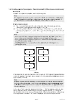
The adjustment screens shown below appear on the LCD.
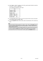
(2) Touch the symbols on the touch panel with a stylus in the order of top-left, bottom-left,
bottom-right, top-right, and the center. After a symbol touched disappears, touch the next
one.
Fig. 5-22
When you press the symbol at the center (the 5th symbol), "OK" appears if the specified area
is correctly adjusted. Then, the machine returns to the initial state of the maintenance mode in
approximately 3 seconds.
In the case of "NG", repeat this operation 2 to 3 times. If "NG" remains displayed even after
the operation is repeated, check if there is harness connection failure in the touch panel,
disconnection, short-circuit, or entry of foreign objects in the touch panel frame. Although any
of these problems is not observed, if "NG" is displayed, replace the touch panel ASSY.
Note:
The adjustment procedure requires a stylus with a thin tip. A commercially available stylus
designed for electronic dictionaries or personal digital assistance (PDA) can be used. If
you do not have it on hand, order the "STYLUS" from the Brother's parts list.
Note:
- Do not use tools other than a pen designed for touch panels. Especially, never use a
pointed one, e.g., a screwdriver. Using such a tool damages the touch panel.
- Do not touch the touch panel with fingers. The contact area of a finger is too large to
adjust the touch panel precisely.
- If the
Stop/Exit
button is pressed, the machine returns to the initial stage of the
maintenance mode.
Note:
If the way to press the symbol is wrong, or if a wrong place is pressed, “ERROR” appears
on the LCD, and the machine returns to the screen in step (2) when the
Start/Black
button
or
Start/Color
button is pressed. Be sure to press the symbols from the upper left in the
order shown above.
Содержание 09055CDN
Страница 22: ...Confidential CHAPTER 1 SPECIFICATIONS ...
Страница 37: ...Confidential CHAPTER 2 ERROR INDICATION AND TROUBLESHOOTING ...
Страница 47: ...2 8 Confidential ADF part A4 model Fig 2 6 Left side Right side Document feed path Face up ...
Страница 48: ...2 9 Confidential ADF part Legal model Fig 2 7 Left side Right side Document feed path Face up ...
Страница 180: ...Confidential CHAPTER 3 DISASSEMBLY AND ASSEMBLY ...
Страница 211: ...3 28 Confidential 8 DISASSEMBLY FLOW Disassembly Re Assembly second ...
Страница 212: ...3 29 Confidential Disassembly Re Assembly second ...
Страница 306: ...3 123 Confidential 2 Remove the Rubber key R from the Panel cover Fig 3 170 Pin Pin Panel cover Rubber key R ...
Страница 358: ...3 175 Confidential 3 Remove the Filter ASSY from the Eject duct Fig 3 260 Eject duct Filter ASSY ...
Страница 394: ...3 211 Confidential 3 Disconnect the Connector from the Waste toner sensor Fig 3 323 Connector Waste toner sensor ...
Страница 416: ...Confidential CHAPTER 4 ADJUSTMENTS AND UPDATING OF SETTINGS REQUIRED AFTER PARTS REPLACEMENT ...
Страница 436: ...Confidential CHAPTER 5 SERVICE FUNCTIONS ...
Страница 445: ...5 7 Confidential Black and white scanning First side Front Fig 5 1 ...
Страница 446: ...5 8 Confidential Black and white scanning Second side Back Fig 5 2 ...
Страница 447: ...5 9 Confidential Color scanning First side Front Fig 5 3 ...
Страница 448: ...5 10 Confidential Color scanning Second side Back Fig 5 4 ...
Страница 475: ...5 37 Confidential Cover page sample Fig 5 18 End page sample Fig 5 19 ...
Страница 482: ...5 44 Confidential Inter color position alignment adjustment chart Fig 5 23 ...
Страница 491: ...5 53 Confidential Color test pattern Fig 5 28 MCYK Y C K M YCMK_ _A ...
Страница 512: ...Confidential CHAPTER 6 CIRCUIT DIAGRAMS WIRING DIAGRAM ...
Страница 514: ...6 1 Confidential 1 CIRCUIT DIAGRAMS High voltage Power Supply PCB Circuit Diagram 1 3 ...
Страница 515: ...6 2 Confidential High voltage Power Supply PCB Circuit Diagram 2 3 ...
Страница 516: ...6 3 Confidential High voltage Power Supply PCB Circuit Diagram 3 3 ...
Страница 517: ...6 4 Confidential Low voltage Power Supply PCB Circuit Diagram 100V ...
Страница 518: ...6 5 Confidential Low voltage Power Supply PCB Circuit Diagram 200V ...
Страница 519: ...6 6 Confidential NCU PCB Circuit Diagram U S A Canada ...
Страница 520: ...6 7 Confidential NCU PCB Circuit Diagram Europe Oceania ...
Страница 521: ...6 8 Confidential NCU PCB Circuit Diagram China Asia South Africa Gulf ...
Страница 523: ...Confidential CHAPTER 7 PERIODICAL MAINTENANCE ...
Страница 581: ...Confidential APPENDIX 1 SERIAL NUMBERING SYSTEM ...
Страница 585: ...Confidential APPENDIX 3 INSTALLING THE MAINTENANCE DRIVER ...
Страница 589: ...App 3 4 Confidential 10 Alert warning message appears click Continue Anyway to proceed ...


