background image

Bronkhorst®

Instruction Manual FLEXI-FLOW™ Compact

9.17.158A

17

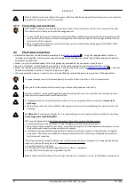
The 

status indication light

 starts blinking blue (1 second on, 1 second off), indicating that the procedure is in progress.

On completion, the indication light assumes the color of the current 

instrument status

.

If the procedure is successful, parameter 

Calibration Mode

 changes to 0 (idle). If the procedure fails, 

Calibration Mode

 changes

to 255.

After zeroing, parameter 

Control Mode

 returns to its initial value. The output signal should be 0 % (parameter 

Measure

 = 0).

After performing the procedure, remember to set parameter 

Init Reset

 to value 0 to lock secured parameters.

3.3

Maintenance

Inexpertly servicing instruments can lead to serious personal injury and/or damage to the instrument or the system it is

used in. Servicing must therefore be performed by trained and qualified personnel. Contact your Bronkhorst representative

for information about cleaning and calibration. Bronkhorst has trained staff available.

The FLEXI-FLOW™ needs no regular maintenance if operated properly, with clean, non-corrosive media, compatible with the

wetted materials, avoiding pressure and thermal shocks and vibrations.

·

Before disconnecting or disassembling any fluid system related parts, always make sure the fluid system is depressurized.

·

When depressurizing, prevent sudden pressure changes by shutting off the fluid supply gradually.

3.3.1

Cleaning

Fluid path

·

The instrument's fluid path (the wetted parts) may be purged with a clean, dry and inert gas.

·

In case of severe contamination, cleaning the wetted parts may be necessary. This requires the instrument to be returned

to the factory.

Exterior parts

The instrument's exterior can be cleaned with a soft, lint free cloth, preferably dry, or, if necessary, moistened with a mild

water soluble cleaning agent.

·

Moisten the cloth only slightly, to prevent liquid from penetrating the instrument's interior and causing damage to the

electrical parts.

·

Only use a water soluble cleaning agent, never an oil based liquid like paint thinner or white spirit, as these might

damage parts made of synthetic materials.

3.3.2

Calibration

The FLEXI-FLOW™ has been factory calibrated. Periodical inspection, recalibration or verification of the accuracy may be

subject to individual requirements of the user. Whenever necessary, contact your Bronkhorst representative for information

and/or making arrangements for recalibration.

Bronkhorst certifies that the instrument meets the rated accuracy. Calibration has been performed using measurement

standards traceable to the Dutch Metrology Institute (VSL).

3.4

Troubleshooting

General problems

·

Electronic problems can be traced by restarting the equipment.

·

If the equipment starts up normally, the measurement and control behavior can be checked by applying fluid pressure.

·

To track down problems in the fluid system, depressurize the fluid system and disconnect the suspected unit from the

process line. Dirt or clogging might be quickly detected by visual inspection of disassembled fluid connections.

If you suspect leakage, do not disassemble the device for inspection, but contact your Bronkhorst representative for service

or repairs.

3.4.1

Zooming in on NAMUR status

Errors and warnings

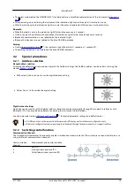
Detailed error and warning information can be found by connecting the instrument to a Windows computer running

FlowSuite. FlowSuite's diagnostic function makes comprehensive diagnostic information accessible based on the 

NAMUR

status

.

7

8

14

Содержание FLEXI-FLOW Compact

Страница 1: ... no 9 17 158 rev A Date 08 04 2022 Instruction Manual ATTENTION Pleaseread this documentcarefully beforeinstalling and operating theproduct Notfollowing theguidelines could resultin personalinjury and ordamageto theequipment ...

Страница 2: ... information and illustration purposes no rights can be derived from its contents Bronkhorst High Tech B V reserves the right to modify or improve its products and documentation without prior notice Device specifications and the contents of the package may deviate from what is stated in this document Symbols in this document Important information Disregardingthisinformationcouldincreasetheriskofda...

Страница 3: ...e technical specifications data sheet for information about required storage conditions Service If you have questions about a product or if you find the product does not meet the specifications as ordered do not hesitate to contact your Bronkhorst representative To enable us to help you quickly and effectively make sure to have the serial number ready whenever seeking contact with your Bronkhorst ...

Страница 4: ...Bronkhorst Instruction Manual FLEXI FLOW Compact 9 17 158A 4 ...

Страница 5: ...ing requirements 2 2 1 11 Fluid connection 2 2 2 12 Preventing pressure shocks 2 2 3 12 2 3 Electrical connection 13 2 4 Fieldbus connection 14 Operation 3 14 3 1 General procedures 14 Powering up 3 1 1 14 First use 3 1 2 14 After use 3 1 3 14 Powering down 3 1 4 14 Understanding instrument status 3 1 5 15 3 2 Special procedures 15 Address selection 3 2 1 15 Switching control function 3 2 2 16 Ena...

Страница 6: ... 3 27 Network configuration 4 2 4 28 Fluid set 4 2 5 29 Advanced fluid set parameters 4 2 5 1 30 Fluid mixture parameters 4 2 5 2 31 Master slave configuration FLOW BUS 4 2 6 32 Digital input and output 4 2 7 32 Device identification 4 2 8 33 Operational history 4 2 9 33 Special parameters 4 2 10 35 4 3 Multi parameter addressing 36 4 4 Gateway multi modular systems 37 Parameter index ...

Страница 7: ...nd machine enclosures applying media and operating conditions as specified in the FLEXI FLOW Compact datasheet Any other use is considered not intended Responsibility for the use of the equipment regarding its intended use suitability for the intended application cleaning and compatibility of process media with the applied materials lies solely with the user Bronkhorst High Tech B V cannot be held...

Страница 8: ...ry the FLEXI FLOW Compact is configured as a mass flow controller An integrated temperature sensor and 2 pressure sensors provide additional real time measurement data allowing the main instrument function to be switched between flow control and pressure control 1 4 4 On board FLUIDAT database A built in database with properties of 22 commonly used gases provides the basis for up to 8 fluid preset...

Страница 9: ...ntheQRcode Type Document name Document no Manuals Instruction Manual FLEXI FLOW Compact this document 9 17 158 Quick Start Guide FLEXI FLOW Compact 9 17 157 Instruction Manual FLOW BUS interface 9 17 024 Instruction Manual Modbus interface 9 17 035 Technical documentation Datasheet technical specifications Hook up diagram Modbus RTU FLOW BUS 9 16 275 Dimensional drawing 7 15 225 Compliance EU Decl...

Страница 10: ...I FLOW makesurethat theequipment hasbeeninstalledandconfiguredbyanauthorized engineer andthat theinstallationisapprovedfor use Toensureandmaintainasafeworkingarea regularlyinspect electrical andfluidlinesandconnections Prior toeachuse checkcablingfor proper connection damageandwear Ifnecessary replacecablesand or connectors Before duringandafter operation checkfluidlinesandconnectionsfor leaks dam...

Страница 11: ...cessconditionsofyour application 2 2 Mounting For optimal performance observethefollowingguidelines Avoidinstallationincloseproximityofmechanical vibrationand or heat sources Usetheequipment inanenvironment withastableambient pressureand temperature For stablefixationtoarigidandstablesurfaceor construction usethethreaded mountingholesinthebottom oftheinstrument base Consult thedimensional drawing ...

Страница 12: ...ower consumption of the application Toprevent damageasaresult ofreversedpolarity theuseofa2A fuseinthedirect Uslineisrecommended Alwaysturnoffelectrical power beforeconnectingor disconnectingequipment electrically Inorder tobeabletocomplywithall applicableguidelinesandregulations it isessential that electrical connectionsbe madebyor under supervisionofaqualifiedelectrician Theequipment describedin...

Страница 13: ...consumptionofyour instrumentsbeforeconnectingthem toafieldbussystem Donot exceed themaximum power ofthepower supplyunit For fieldbusrelatedwiringdetails consult theaccordinghook updiagram For informationabout settingupafieldbusnetworkwithBronkhorst instruments consult theaccordingfieldbus manual Ifyouneedassistancewithsettingupafieldbusnetwork contactyour Bronkhorst representativefor information 9...

Страница 14: ...ctronics and perform a self test During initialization the indication light cycles through all NAMUR status colors After successful initialization the indication light lights up green to indicate that the instrument is ready to be used 3 1 2 First use Bronkhorst doestheutmost toensurethat youreceiveacleanproduct Thisdoesnot however relievetheuser ofthe responsibilitytoensurethat theequipment andth...

Страница 15: ...addressselection Assuming the default baud rate and parity match the fieldbus settings the fieldbus address can be quickly set using the manual address selector With value 0 the instrument uses the digital address setting Values from 1 to 9 override the digital setting Digitalnetwork settings FlowSuite can be used to set the fieldbus address baud rate and parity digitally through the support inter...

Страница 16: ...process conditions the zero point will remain stable However over time several factors can induce a slight deviation of the measured value from the zero point causing the instrument to detect a flow when in reality there is none Readjusting the zero point eliminates this deviation After installationor relocation alwayscheckthezeropoint Iftheinstrument still detectsa steady flowwhileall valvesarecl...

Страница 17: ...o be returned to the factory Exterior parts The instrument s exterior can be cleaned with a soft lint free cloth preferably dry or if necessary moistened with a mild water soluble cleaning agent Moistentheclothonlyslightly toprevent liquidfrom penetratingtheinstrument sinterior andcausingdamagetothe electrical parts Onlyuseawater solublecleaningagent never anoil basedliquidlikepaint thinner or whi...

Страница 18: ...ntact your Bronkhorst representative Control behavior unstable Measurement disturbed by vibrations If possible avoid installation in close proximity of mechanical vibration Reduce sensitivity to vibrations by using a mass block shock absorbers and flexible tubing Inlet pressure unstable Install pressure regulator or increase buffer volume between controlling instruments Inlet and or outlet pressur...

Страница 19: ... adapters tubing valves Zero point adjustment performed incorrectly Readjust zero point following instructions in Adjusting zero point Continuous maximum measured value or output signal Inlet pressure too high Check inlet pressure Valve fully open Close valve In case of normally open valve check if valve is in safe state resolve cause if necessary see Default valve state Sensor failure Contact you...

Страница 20: ... bronkhorst com Important Clearly note on top of the package the customs clearance number of Bronkhorst High Tech B V NL801989978B01 only if applicable otherwise contact your Bronkhorst representative for local arrangements 3 5 2 Disposal end of lifetime If you are a customer within the European Union and wish to dispose of Bronkhorst equipment bearing the symbol of a crossed out waste disposal bi...

Страница 21: ...ird party development software like LabVIEW or a SCADA platform TheFlowWaretoolsandassociateddocumentationcanbedownloadedfrom theproduct pagesontheBronkhorst website www bronkhorst com flexi flow Modbus In a Modbus system instruments can be monitored and operated using third party software as a master device such as LabVIEW ModScan or a Modbus PLC 4 2 Parameters A summaryofall digital parametersin...

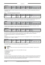
Страница 22: ...tailedinformationabout settingupaModbusnetworkwithBronkhorst instruments consult theModbus manual seeDocumentation 4 2 1 Measurement and control Measure Type Access Range FlowDDE FLOW BUS Modbus Unsigned int R 0 41942 8 1 0 0x0020 33 This parameter indicates the flow metered by the instrument The value of 32000 corresponds to 100 the maximum measured value output is 131 07 which translates to 4194...

Страница 23: ...ould take to adjust the setpoint if it were changed from 0 to 100 This feature can be used to smooth nervous controller behavior e g to reduce setpoint overshoot or undershoot The supported range corresponds to 0 3000 seconds Default value 0 Example If Setpoint Slope 100 it will take 10 seconds to adjust the setpoint if it is changed from 0 to 100 A setpoint change of 20 will take 20 100 10 second...

Страница 24: ...y caused by a power dip If combined with bit 2 or 3 Response alarm Difference between Measure and Setpoint too big 6 64 Master slave alarm Setpoint out of limits caused by Slavefactor 7 128 Hardware alarm Hardware error AlarmDelayTime Type Access Range FlowDDE FLOW BUS Modbus Unsigned char RW 0 255 182 97 7 0x0C27 3112 This value represents the time in seconds the alarm action will be delayed when...

Страница 25: ...ault value 15 all bits methods enabled The following methods are supported Bit Value Description 0 1 By hardware switch if present 1 2 Externally obsolete 2 4 By parameter Reset 3 8 Automatically when alarm conditions no longer apply 4 2 3 Counter Counter settingsaremost easilyaccessibleusingFlowSuite FlowPlot or FlowViewor aBronkhorst readout andcontrol unit Whentheinstrument ispowereddown it rem...

Страница 26: ...e FlowDDE FLOW BUS Modbus Unsigned char RW 0 1 126 104 5 0x0D05 3334 Specifies whether or not to change the setpoint after reaching the counter limit Value Description 0 No setpoint change default 1 Change setpoint to Counter newsetpoint Counter New Setpoint Type Access Range FlowDDE FLOW BUS Modbus Unsigned int RW 0 32000 127 104 6 0x0D06 3335 New safe setpoint when a counter limit is reached unt...

Страница 27: ...ter Totalizer Unit 4 2 4 Network configuration Changesmadetothenetworksettingswill not berestoredbyafactoryreset Ifthemanual addressselector isset toavalueother than0 it overridesthedigital addresssetting Fieldbus1 Address Type Access Range FlowDDE FLOW BUS Modbus Unsigned char RW B 0 255 199 125 10 0x0FAA 4011 Fieldbus1 Baud Rate Type Access Range FlowDDE FLOW BUS Modbus Unsigned long RW B 0 1 0E...

Страница 28: ...d fluids up to 8 can be selected Each fluid has its specific configurable properties such as FluidName Capacity etc Default value 0 fluid 1 Note that the selected value is equal to the fluid number minus 1 value 0 corresponds to fluid 1 value 1 to fluid 2 etc Fluid Name Type Access Range FlowDDE FLOW BUS Modbus Unsigned char 10 RW B 25 1 17 0x8188 0x818C 33161 33165 This parameter contains the nam...

Страница 29: ...tancemm3n m means mm3n min CapacityUnitTypeTemperature Type Access Range FlowDDE FLOW BUS Modbus Float RW B 273 15 3 4E 38 245 33 10 0xA150 0xA151 41297 41298 This parameter defines a reference temperature for conversion of the measured mass flow to a volume flow See also parameters CapacityUnit and Counter Unit CapacityUnitTypePressure Type Access Range FlowDDE FLOW BUS Modbus Float RW B 0 3 4E 3...

Страница 30: ...y of the current fluid in W m K Viscosity Type Access Range FlowDDE FLOW BUS Modbus Float RW B 0 3 4E 38 252 113 21 0xF1A8 0xF1A9 61865 61866 Dynamic viscosity of the current fluid in Pa s 4 2 5 2 Fluid mixture parameters MixFraction Type Type Access Range FlowDDE FLOW BUS Modbus Unsigned char RW B 0 2 346 126 4 0x0FC4 4037 Set the fraction type of the mixture Value Description 0 Volume fraction 1...

Страница 31: ...in a fieldbus system The FLOW BUS protocol however provides a feature to set up a master slave relationship between two instruments The typical behavior of a slave instrument is to automatically set its own setpoint relative to the output measurement value of its master The output value of any instrument in a FLOW BUS network is automatically available to all other instruments without extra wiring...

Страница 32: ...o actuate the valve Depending on the valve type actuation leads to closing or opening the valve Value Description Normally open Normally closed 0 Inactive open closed 1 Active closed open Immediatelyafter powering up IO Switch Status isinactive Intheevent ofcommunicationfaults theshut offvalvewill fall backtoitsdefault state 4 2 8 Device identification User Tag Type Access Range FlowDDE FLOW BUS M...

Страница 33: ...0x0EC2 1 BHT3 Flow Time Unsigned long R 96 118 3 0xF618 2 BHT4 Actuation Count Unsigned int R 97 118 4 0x0EC4 1 BHT5 Mode Change Count Unsigned char R 98 118 5 0x0EC5 1 BHT6 Watchdog Reset Count Unsigned char R 99 118 6 0x0EC6 1 BHT7 Power Cycle Count Unsigned char R 100 118 7 0x0EC7 1 BHT8 Normal Reset Count Unsigned char R 101 118 8 0x0EC8 1 BHT9 NVRAM Error Count Unsigned long R 102 118 9 0xF64...

Страница 34: ... seconds This can be useful in order to identify a specific device in a large fieldbus network Modbus requires the following values No of seconds Wink value 1 12544 2 12800 3 13056 4 13312 5 13568 6 13824 7 14080 8 14336 9 14592 ControlMode Type Access Range FlowDDE FLOW BUS Modbus Unsigned char RW 0 255 12 115 1 0x0024 37 Control Mode is used to select different control modes of the instrument an...

Страница 35: ...ication is consistent with section Parameters See the according subsections for detailed parameter descriptions Generaladdressderivation using offset In a Modbus system parameters of communication channels 2 and 3 can be accessed by applying an offset to the Modbus PDU address of the channel 1 parameter For address range 0x0000 0x0FFF add 0x20 to the Modbus PDU address for channel 2 or 0x40 for ch...

Страница 36: ... 98 2 0x0C42 99 2 0x0C62 Alarm Mode 118 97 3 0x0C23 98 3 0x0C43 99 3 0x0C63 Alarm Setpoint Mode 120 97 5 0x0C25 98 5 0x0C45 99 5 0x0C65 Alarm New Setpoint 121 97 6 0x0C26 98 6 0x0C46 99 6 0x0C66 Alarm Delay Time 182 97 7 0x0C27 98 7 0x0C47 99 7 0x0C67 Reset Alarm Enable 156 97 9 0x0C29 98 9 0x0C49 99 9 0x0C69 4 4 Gateway multi modularsystems On communication platforms other than FLOW BUS or Modbus...

Страница 37: ...mperature 29 Fluid Name 28 Fluid Set Index 28 Parameters Fluid set advanced Density 30 Fluid Temperature 30 Heat Capacity 30 Inlet Pressure 29 Outlet Pressure 29 Thermal Conductivity 30 Viscosity 30 Parameters Fluid set mixture Mix Component Fluid Name 31 Mix Component Fraction 31 Mix Component Index 31 Mix Fraction Type 30 Mix Volume Pressure 30 Mix Volume Temperature 30 Parameters Master Slave M...

Отзывы: