Page 1/26
IOM Single Case BiRotor Plus R06
Installation & Operation Manual
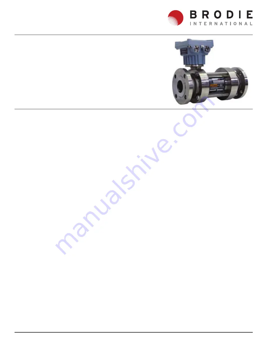
BiRotor Plus2” Single Case
Страница 1: ...Page 1 26 IOM Single Case BiRotor Plus R06 Installation Operation Manual BiRotor Plus 2 Single Case...
Страница 2: ...Page 2 26 IOM Single Case BiRotor Plus R06...
Страница 3: ...General 10 2 Removal Replacement of Circuit Board 10 3 Removal Replacement of Pick Off Sensors 10 4 Removal of the Measuring Unit from the Process Line 10 5 Removal of the Measuring Unit from the Inst...
Страница 4: ...ontents of this publication are presented for informational purposes only and while every effort has been made to ensure their accuracy they are not to be construed as warranties or guarantees express...
Страница 5: ...ed with in the instruction manual or marked on the instruments name plates Install the equipment as specified in the installation instructions of the appropriate manual and in accordance to local and...
Страница 6: ...custody transfer label this label details the working flow range associated with a particular weights and measures approval It should be noted that these may not be the same therefore in trade applic...
Страница 7: ...e or uncontrolled chemical reactions It is the end users responsibility to provide fire protection measures and equipment in accordance with the local regulations It is the end users responsibility to...
Страница 8: ...ust be made from stainless steel grade A1 70 or A2 70 and be torqued to a value of 55 in lbs upon installation its is the end users responsibility to ensure this happens It is the end users responsibi...
Страница 9: ...cing the instrument upright on the inlet flange will aid drainage Process connections must be sealed to prevent leakage of residual product during shipment Contact the local carrier for information on...
Страница 10: ...ting parts Principle of Operation The operation of the meter is embodied in the function of the measuring rotors they are always dynamically balanced but hydraulically unbalanced during operation The...
Страница 11: ...y Voltage Less 5 70 mA max Open Collector Max voltage 30 VDC Max current 125 mA Max power 0 5 W Performance SB25X Linearity Standard Rotors 0 15 Over Standard Flow Range 0 25 Over Extended Flow Range...
Страница 12: ...suitable hardware as specified in the local codes and regulations Ensure that the connections are made tight and torqued to the correct values 3 Connect the instrument wiring refer to Figures 9 1 and...
Страница 13: ...must be closed all electrical connections are complete and all covers are in place 1 To pressurize the system slowly open the inlet valve so as to prevent system shock Slowly allow product to enter t...
Страница 14: ...low the temperature to stabilize 9 3 Custody Transfer A meter factor will need to be established under actu al operating conditions if the instrument is to be used in custody transfer applications Thi...
Страница 15: ...l measuring element contains closely meshed moving parts care should be taken not to insert figures into the rotors or timing gears as this will cause injury NOTE All Item Numbers referenced in this s...
Страница 16: ...sor in the sensor housing If only one pick off sensor is present it should be inserted in the hole labelled A Secure with the hold down washer and Allen screws and replace the circuit board 10 4 Remov...
Страница 17: ...rew from the end plate at the timing gear end of the measuring unit assembly NOTE A flat head screwdriver may be used in conjunction with the slots on the end plate to aid in its removal Excessive for...
Страница 18: ...ing unit housing on it s side so that the name plate label in on the bottom and the outlet end facing away from you Then with the tapered ands of the rotors also facing away from you the right hand ro...
Страница 19: ...ht hand timing gear to a torque setting of 35 in lbs 3 Loosen the nut of the left hand timing gear 4 Place 0 003 shims in front and behind the tooth of the left hand rotor Once the shims are in place...
Страница 20: ...information consult factory Whenordering the following information must be furnished 1 Part number and description 2 Model number of flow meter 3 Serial number of flow meter 4 Quantity required When o...
Страница 21: ...Page 21 26 IOM Single Case BiRotor Plus R06 Figure 11 1 Complete Measuring Unit Assembly...
Страница 22: ...150 ANSI MTR s 1 56819 100N Outlet Housing 150 ANSI MTR s and NACE 56819 040M Outlet Housing DIN PN 16 and PN 40 MTR s 56819040N Outlet Housing DIN PN 16 and PN 40 MTR s and NACE 56819 300M Outlet Hou...
Страница 23: ...1500909D Approved Stopping Plug 1 43 SD442 Plastic Cap Plug 1 Table 11 1 Parts List Single Case BiRotor Plus Continues Notes Items marked with a are recommended spare parts 1 These items are only ava...
Страница 24: ...ction 7 Specifications Power failure Ensure power is connected to the device and all associated accessories Meter rotors jammed with debris Remove debris from rotors and check for damage to rotors tim...
Страница 25: ...ie are not covered by this limited warranty and shall be at Buyer s expense Brodie shall not be obligated to pay any costs or charges incurred by Buyer or any other party except as may be agreed upon...
Страница 26: ...m or cause of action Buyer agrees that in no event shall Brodie s liability to buyer and or its customers extend to include incidental consequential or punitive damages The term consequential damages...