


3. Tighten the captive for each ejector using a #1 Phillips screwdriver.
NOTE
Be sure that captive screws are tightened. If not, high pressure from fan operation may unseat blade from chassis
connectors.
4. Power up the device.
5. Connect the cables to the new CP blades.
6. Enter
chassisDisable
.
7. Enter
configDownload -vf
to download device virtual fabric data to the local system.
The device reboots and partitions are restored.
8. Enter
chassisDisable
.
9. Enter
configDownload -map
to download port-to-area addressing mode configuration files to the local system.
10. Power-cycle the chassis.
The system recovers.
11. Enter
chassisDisable
.
12. Enter
configDownload -all
to download system configuration data, including chassis and switch configuration for all logical
switches, to the local system.
All the licenses, configurations, and FCIP tunnels are restored.
13. Enter
reboot
.
The device becomes fully functional with the new CP blades.
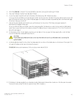
14. Verify that each blade's power LED is green. If not, ensure that the CP blade has power and is firmly seated and that the ejectors
are in the locked position.
Completing the replacement
Complete the following steps to complete the CP blade replacement procedure.
1. Enter
haEnable
to re-enable HA on the active CP blade.
NOTE
The
haEnable
command will cause the standby CP blade to reboot. Wait until POST completes before moving to the
next step. POST is complete when the status LED on the CP blade returns to a steady green state.
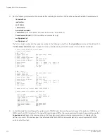
2. Enter
haShow
and verify that the command output includes "HA Enabled, Heartbeat Up". If it is not yet enabled, re-enter the
command until you have verified that redundancy is achieved.
NOTE
The
haEnable
command will cause the standby CP blade to reboot.
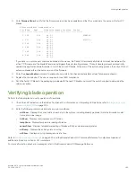
Chassis_1:admin> hashow
Local CP (Slot 2, CP1) : Active
Remote CP (Slot 1, CP0) : Standby, Healthy
HA Enabled, Heartbeat Up, HA State Synchronized
Replacing a CP blade
Brocade X6-4 Director Hardware Installation Guide
164
53-1004106-07
Содержание X6-4
Страница 12: ...Brocade X6 4 Director Hardware Installation Guide 12 53 1004106 07...
Страница 20: ...Brocade X6 4 Director Hardware Installation Guide 20 53 1004106 07...
Страница 28: ...Brocade X6 4 Director Hardware Installation Guide 28 53 1004106 07...
Страница 64: ...Brocade X6 4 Director Hardware Installation Guide 64 53 1004106 07...
Страница 86: ...Brocade X6 4 Director Hardware Installation Guide 86 53 1004106 07...
Страница 102: ...Brocade X6 4 Director Hardware Installation Guide 102 53 1004106 07...
Страница 130: ...Brocade X6 4 Director Hardware Installation Guide 130 53 1004106 07...
Страница 140: ...Brocade X6 4 Director Hardware Installation Guide 140 53 1004106 07...
Страница 166: ...Brocade X6 4 Director Hardware Installation Guide 166 53 1004106 07...
Страница 196: ...Brocade X6 4 Director Hardware Installation Guide 196 53 1004106 07...
Страница 200: ...Brocade X6 4 Director Hardware Installation Guide 200 53 1004106 07...
Страница 204: ...Brocade X6 4 Director Hardware Installation Guide 204 53 1004106 07...
Страница 210: ...Brocade X6 4 Director Hardware Installation Guide 210 53 1004106 07...
Страница 224: ...Brocade X6 4 Director Hardware Installation Guide 224 53 1004106 07...
Страница 238: ...Brocade X6 4 Director Hardware Installation Guide 238 53 1004106 07...