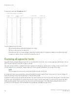


Each numbered QSFP port on the blade provides four 32 Gbps FC ports. The following table shows the mappings from the numbered
QSFP ports on the face of the core blade to the individual FC port numbers as shown by the
slotShow
command.
TABLE 24
External port to slotShow port mapping for core blades
External port number
slotShow
FC port numbers
0
0-3
1
4-7
2
8-11
3
12-15
4
16-19
5
20-23
6
24-27
7
28-31
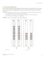
ICL trunking groups
Multiple directors can be connected through inter-chassis links (ICLs) between 4x32-Gbps QSFPs on core routing blades installed in
these devices. Each QSFP connection between two devices provides 128 Gbps bandwidth. Trunking optimizes the use of ICL
bandwidth by allowing a group of links to merge into a single logical link, called a trunk. Traffic is distributed dynamically and in order over
this trunk, achieving greater performance with fewer links. Within the trunk, multiple physical ports appear as a single port, thus
simplifying management. Trunking also improves system reliability by maintaining in-order delivery of data and avoiding I/O retries if one
link within the trunk fails.
Each QSFP provides four 32 Gbps FC ports. Since each port within a QSFP terminates on a different ASIC within each core blade, an
ICL trunk cannot be formed using the individual FC ports within the same QSFP. A trunk has to be formed from individual FC ports in
different QSFP ports. These QSFP ports must reside in the same trunk group. To form an ICL trunk between two devices, a minimum of
two QSFPs within a port trunk group on a core blade installed in one device must be connected to a pair of QSFPs within a trunk group
on a core blade in another device using ICLs.
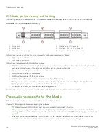
Each CR32-4 blade on the Brocade X6-4 has two ICL trunking groups consisting of the following QSFP ports:
•
0, 1, 5, and 4
•
2, 3, 6, and 7
Ports belonging to the same trunking groups are indicated with the same color border under the ports on the blade faceplate. These
colors are also applied to the port map labels on each blade faceplate to indicate ports belonging to the same trunking groups.
For more information on ICLs and configuring ICL trunking between core routing blades on GEN6 and GEN5 Directors, refer to the
"Inter-Chassis Links" in the
Brocade Fabric OS Administration Guide
.
For more information recommended cabling topologies for ICLs, refer to
NOTE
You cannot configure ISLs using ports on port blades and QSFP-based ICLs using ports on core routing blades concurrently
on the same chassis.
Core routing blade overview
Brocade X6-4 Director Hardware Installation Guide
142
53-1004106-07
Содержание X6-4
Страница 12: ...Brocade X6 4 Director Hardware Installation Guide 12 53 1004106 07...
Страница 20: ...Brocade X6 4 Director Hardware Installation Guide 20 53 1004106 07...
Страница 28: ...Brocade X6 4 Director Hardware Installation Guide 28 53 1004106 07...
Страница 64: ...Brocade X6 4 Director Hardware Installation Guide 64 53 1004106 07...
Страница 86: ...Brocade X6 4 Director Hardware Installation Guide 86 53 1004106 07...
Страница 102: ...Brocade X6 4 Director Hardware Installation Guide 102 53 1004106 07...
Страница 130: ...Brocade X6 4 Director Hardware Installation Guide 130 53 1004106 07...
Страница 140: ...Brocade X6 4 Director Hardware Installation Guide 140 53 1004106 07...
Страница 166: ...Brocade X6 4 Director Hardware Installation Guide 166 53 1004106 07...
Страница 196: ...Brocade X6 4 Director Hardware Installation Guide 196 53 1004106 07...
Страница 200: ...Brocade X6 4 Director Hardware Installation Guide 200 53 1004106 07...
Страница 204: ...Brocade X6 4 Director Hardware Installation Guide 204 53 1004106 07...
Страница 210: ...Brocade X6 4 Director Hardware Installation Guide 210 53 1004106 07...
Страница 224: ...Brocade X6 4 Director Hardware Installation Guide 224 53 1004106 07...
Страница 238: ...Brocade X6 4 Director Hardware Installation Guide 238 53 1004106 07...