background image

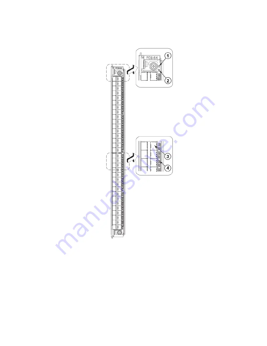
FIGURE 19 

FC8-64 Port blade

1. Status LED
2. Power LED
3. Fibre Channel port
4. Port Status LED

NOTE

The FC8-64 port blade requires narrower OM-3 LC cables offered by major manufacturers like Corning, Molex, and
Amphenol.

Determining the status of a port, application, or encryption blade

Brocade DCX Backbone Hardware Installation Guide

53-1000685-24

67

Содержание DCX Backbone

Страница 1: ...HARDWARE INSTALLATION GUIDE Brocade DCX Backbone Hardware Installation Guide 53 1000685 24 28 February 2017...

Страница 2: ...ocument describes features that may not be currently available Contact a Brocade sales office for information on feature and product availability Export of technical data contained in this document ma...

Страница 3: ...ty 21 Serviceability 21 Software features 22 Security 22 Network manageability 23 Preparing for the Installation 25 Installation and safety considerations 25 Time and items required for installation 2...

Страница 4: ...Software licenses 59 Installing transceivers and attaching cables 60 Managing cables 60 Verifying correct operation and backing up the configuration 61 Powering off the Brocade DCX 62 Monitoring Syst...

Страница 5: ...103 Time and items required 103 Removing a blower assembly 103 Replacing a blower assembly 104 WWN card removal and replacement 105 Time and items required 105 Using the wwnrecover utility 106 Verifyi...

Страница 6: ...Statements 157 BSMI statement Taiwan 157 Canadian requirements 157 CE statement 157 China ROHS 158 FCC warning US only 158 KCC statement Republic of Korea 158 VCCI statement 158 Brocade DCX Backbone T...

Страница 7: ...Caution and Danger Notices 165 Cautions 165 Danger notices 166 Brocade DCX Backbone Hardware Installation Guide 53 1000685 24 7...

Страница 8: ...Brocade DCX Backbone Hardware Installation Guide 8 53 1000685 24...

Страница 9: ...interrupted or the device might reboot CAUTION A Caution statement alerts you to situations that can be potentially hazardous to you or cause damage to hardware firmware software or data DANGER A Dan...

Страница 10: ...esources Visit the Brocade website to locate related documentation for your product and additional Brocade resources White papers data sheets and the most recent versions of Brocade software and hardw...

Страница 11: ...d Sev 2 High issues Continental US 1 800 752 8061 Europe Middle East Africa and Asia Pacific 800 AT FIBREE 800 28 34 27 33 Toll free numbers are available in many countries For areas unable to access...

Страница 12: ...Brocade DCX Backbone Hardware Installation Guide 12 53 1000685 24...

Страница 13: ...out RTC NVRAM batteries in Hardware components on page 15 Editorial changes to sections in GUID 25F4B3AC 7D35 4DBB A847 68D335839B41 ditamap Added notes to following sections directing users replacing...

Страница 14: ...Brocade DCX Backbone Hardware Installation Guide 14 53 1000685 24...

Страница 15: ...only Up to 1024 ports in the same rack can connect with the use of inter chassis links ICLs Up 1536 ports can be connected via ICLs in adjacent racks Support for high performance port blades running a...

Страница 16: ...8 18 Modular hot swappable encryption blades FS8 18 16 port up to 4 blades per chassis supporting data cryptographic encryption decryption and data compression capabilities Modular hot swappable field...

Страница 17: ...perature monitoring Port side of the Brocade DCX NOTE Airflow in the Brocade DCX is from the nonport noncable side to the port cable side and out the exhaust vent The following illustration displays a...

Страница 18: ...ade DCX FIGURE 2 Nonport side of the Brocade DCX sample configuration 1 WWN bezel logo plate 2 Power supply 4x 3 Blower assembly 3x Brocade DCX blades The following table summarizes the port applicati...

Страница 19: ...e port blade supporting 1 2 4 and 8 Gbps port speeds This port blade is compatible with the Brocade 48000 Director Brocade DCX and Brocade DCX 4S 64 port 8 Gbps port blade FC8 64 A 64 port Brocade por...

Страница 20: ...ft set of ports 32 through 63 from bottom to top on the right set of ports 0 7 8 15 16 23 24 31 32 39 40 47 48 55 and 56 63 FS8 18 blade FC ports 0 through 15 from bottom to top 10 100 1000 BaseT port...

Страница 21: ...dancy checking CRC parity checking checksum and illegal address checking Power on self test POST Dual control processors that enable hot nondisruptive fast firmware upgrades One serial port and two Et...

Страница 22: ...her Brocade enterprise class products running Fabric OS 5 2 0 or later For details contact your Brocade DCX supplier and refer to the Brocade White Paper The Growing Need for Security in Storage Area...

Страница 23: ...ement interfaces such as Telnet Web Tools standards compliant SMI S and Management Server support a port N within blade M naming scheme The Brocade DCX supports SNMPv1 and SNMPv3 When SNMP devices sen...

Страница 24: ...Brocade DCX Backbone Hardware Installation Guide 24 53 1000685 24...

Страница 25: ...ilable 200 240 VAC 50 60 Hz two branch circuits 110 120 VAC 50 60 Hz up to four branch circuits Two cables for 200 240 VAC service up to four cables for 110 120 VAC service Power supply standards are...

Страница 26: ...nstallation tasks time and items required Installation task Time estimate Items required Site preparation and unpacking Brocade DCX 30 minutes 1 2 in socket wrench to remove pallet bolts 2 Phillips sc...

Страница 27: ...re switch blade WWN cards WWN bezel logo plate Power supplies Power supply filler panels included if there are fewer than four power supplies Blower assemblies Cable management comb Chassis door Acces...

Страница 28: ...Brocade DCX Backbone Hardware Installation Guide 28 53 1000685 24...

Страница 29: ...e aisle The device can be installed facing either direction if serviceability and cooling requirements are met Ensure that the air intake and exhaust vents have a minimum of 5 1 cm 2 in of airspace En...

Страница 30: ...ed shelf brackets designed for specific racks Refer to Installing the 14U Rack Mount Kit for Four Post Racks XBR DCX 0120 and XBR DCX 0152 on page 31 for instructions In a two post Telco rack Use the...

Страница 31: ...ation surface ensuring that it remains supported during the transfer 10 Ensure that the chassis is oriented so that the nonport side has access to intake air cool 11 Reinstall the cable management com...

Страница 32: ...es shown in illustration All 1 Right rack mount shelf bracket rail brackets may differ from ones shown in illustration All 1 10 32 x 5 8 in 1 58 cm panhead Phillips screw and washer torque to 32 in lb...

Страница 33: ...s that have rails with square holes 8 3 8 in 0 953 cm alignment washer for cabinets that have rails with square holes Parts list NEBS kit The following table lists the parts supplied in the XBR SLX985...

Страница 34: ...tainer 6 Assembling the rack hardware Attach the left and right rack mount shelf brackets to the rack rails NOTE If cables are to be routed down through the cable management comb allow space below the...

Страница 35: ...ket 16 total 4 3 8 in 0 953 cm alignment washer for rails with square holes 4 on each end of each bracket 16 total 5 1 4 20 x 1 2 in 1 27 cm panhead Phillips screw with thread locker for rails with sq...

Страница 36: ...Tighten the screws to a torque of 80 in lb 92 cm kg FIGURE 6 Nut and screw locations for mounting the device 1 10 32 clip nuts for round holes 2 Rail 3 10 32 retainer nut for square holes 4 Rail 5 Top...

Страница 37: ...talling the device in the rack Use the following procedure to install the device in the rack DANGER Use safe lifting practices when moving the product 1 Ensure that the door if installed is removed fr...

Страница 38: ...s supported during the transfer FIGURE 7 Positioning the device for installation in a rack 1 Rack 2 Nonport side of device Installing the 14U Rack Mount Kit for Four Post Racks XBR DCX 0120 and XBR DC...

Страница 39: ...illips screw with washer 7 Reinstall the device door if removed from your device For instructions refer to the door removal and replacement procedures in your device installation guide Installing the...

Страница 40: ...e and Items required Allow approximately one hour to unpack and install a chassis in a rack The following tools are required when installing the 14U Chassis Mid Mount Rack Kit for Two Post Racks Torqu...

Страница 41: ...type Assembling the rack hardware Perform the following steps to assemble the rack hardware 1 Attach the rear tray with or without adapter as required to both rack rails Orient the tray refer the fol...

Страница 42: ...IGURE 10 Attaching the rear tray to the rack rails 2 Tray rear mid mount chassis 3 Adapter rear mid mount right 4 Adapter rear mid mount left 5 Screws Installing the 14U Chassis Mid Mount Rack Kit for...

Страница 43: ...vice in the rack DANGER Use safe lifting practices when moving the product NOTE A fully populated device requires a hydraulic or assisted lift to install into a rack Installing the 14U Chassis Mid Mou...

Страница 44: ...cable lock the wheels of the lift 4 Slide the device into the trays until the front edge of the device is seated against the front tray FIGURE 12 Placing the device in the trays 1 Tray front mid mount...

Страница 45: ...ottom holes of the Brocade mounting bracket because the door will interfere with the screw heads FIGURE 13 Attaching trays to the device 8 Reinstall the device door For instructions refer to the door...

Страница 46: ...Brocade DCX Backbone Hardware Installation Guide 46 53 1000685 24...

Страница 47: ...nsceiver is smaller than in standard SFPs Patch cables and panels can be used to attach standard size cabling to the blade if necessary The following figure illustrates the mSFP to SFP patch cable See...

Страница 48: ...SFP LC standard LC duplex multi mode OM3 50 125 10 m S50502S5120010M 106273 0529 943 99865 10010 Patch cables mSFP to mSFP S5S502S5120XXXM XXX length 943 99866 1XXXX XXXX length mSFP LC mSFP LC duplex...

Страница 49: ...olex part number Amphenol part number Bag of clips quantity 64 TRIGGER BP NP n a n a Installing ICL cables optional Go to Removal and replacement of the inter chassis link ICL cables on page 115 for t...

Страница 50: ...Brocade DCX Backbone Hardware Installation Guide 50 53 1000685 24...

Страница 51: ...nfiguration 61 Powering off the Brocade DCX 62 Items required The following items are required for initial setup and verification of the device The device mounted and installed with the required blade...

Страница 52: ...blePost command ATTENTION Do not connect the switch to the network until the IP addresses are configured Configuring the Brocade DCX The Brocade DCX must be configured before it is connected to the fa...

Страница 53: ...ect the CONSOLE port on the active CP to a computer workstation The active CP blade is indicated by an illuminated blue LED ATTENTION The CONSOLE port is intended primarily for the initial setting of...

Страница 54: ...ial login Make sure to write down the new passwords and keep this information in a secure location Fabric OS swDir swDir login admin Password Please change your passwords now Use Control C to exit or...

Страница 55: ...ommand swDir admin ipAddrSet cp 0 Enter the information at the prompts 4 Set up the CP1 IP address by entering the ipaddrset cp 1 command swDir admin ipAddrSet cp 1 Enter the information at the prompt...

Страница 56: ...rt one end of an Ethernet cable into the Ethernet port 3 Connect the other end to an Ethernet 10 100 1000 BaseT LAN The Brocade DCX can be accessed through a remote connection using any of the managem...

Страница 57: ...r switchDisable to disable the Brocade DCX 2 Enter configure 3 Enter y at the Fabric parameters prompt Fabric parameters yes y no n no y 4 Enter a unique domain ID Domain 1 239 1 3 5 Complete the rema...

Страница 58: ...ollows switch admin tstimezone interactive timezone_fmt Use timezone_fmt to set the time zone by Country City or by time zone ID such as MST The following example shows how to change the time zone to...

Страница 59: ...ver 132 163 135 131 switch admin tsclockserver 132 163 135 131 switch admin The following example shows how to set up more than one NTP server using a DNS name switch admin tsclockserver 10 32 170 1 1...

Страница 60: ...le into the transceiver until the latching mechanism clicks Cables are keyed so that they can be inserted in only one way If a cable does not slide in easily ensure that it is correctly oriented 3 Rep...

Страница 61: ...of the Brocade DCX by entering the switchShow command from the workstation This command provides information about switch and port status 4 Verify the correct operation of the Brocade DCX in the fabr...

Страница 62: ...down the blade Stopping blade 2 Shutting down the blade Stopping blade 8 Shutting down the blade Broadcast message from root pts 1 Tue Aug 23 14 23 06 2008 The system is going down for system halt NOW...

Страница 63: ...mands Refer to the Brocade Web Tools Administration Guide and the Brocade Fabric OS Administration Guide for additional information Determining the status of a port application or encryption blade 1 C...

Страница 64: ...ng slotShow FIGURE 16 FC8 16 Port blade 1 Power LED 2 Status LED 3 Fibre Channel port 4 Port Status LED Determining the status of a port application or encryption blade Brocade DCX Backbone Hardware I...

Страница 65: ...C8 32 Port blade 1 Power LED 2 Status LED 3 Fibre Channel port 4 Port Status LED Determining the status of a port application or encryption blade Brocade DCX Backbone Hardware Installation Guide 53 10...

Страница 66: ...C8 48 Port blade 1 Power LED 2 Status LED 3 Fibre Channel port 4 Port Status LED Determining the status of a port application or encryption blade Brocade DCX Backbone Hardware Installation Guide 66 53...

Страница 67: ...4 Port Status LED NOTE The FC8 64 port blade requires narrower OM 3 LC cables offered by major manufacturers like Corning Molex and Amphenol Determining the status of a port application or encryption...

Страница 68: ...18 Encryption blade 1 Power LED 2 Status LED 3 Fibre Channel port 4 Port Status LED Determining the status of a port application or encryption blade Brocade DCX Backbone Hardware Installation Guide 68...

Страница 69: ...1 Power LED 2 Status LED 3 GbE port 6 4 GbE port 6 LED 5 10GbE port 0 6 10GbE port 0 LED 7 Port map Determining the status of a port application or encryption blade Brocade DCX Backbone Hardware Inst...

Страница 70: ...ibes the port and application blade LED patterns and the recommended actions for those patterns TABLE 6 Port and application blade LED descriptions LED purpose Color Status Recommended action Power LE...

Страница 71: ...uired Slow flashing green on 1 second then off 1 second Port is online but segmented indicating a loopback plug or cable or an incompatible switch Verify that the correct device is attached to the Bro...

Страница 72: ...equired Flickering green Port is online with traffic flowing through port No action required Steady amber Port is receiving light but it is not online yet Reset the port by doing a shutdown and no shu...

Страница 73: ...ol processor blade CP8 1 Power LED 2 Status LED 3 USB LED 4 USB port 5 Console port 10101 6 Ethernet port MGM IP 7 Ethernet port SERVICE IP 8 Active CP LED Determining the status of a control processo...

Страница 74: ...D is off Either an Ethernet link is not detected or it does not have incoming power Ensure that the blade has power the Ethernet cable is firmly seated and the connected device is functioning Flickeri...

Страница 75: ...CR8 1 Power LED 2 Status LED 3 LINK LED 4 ATTN LED 5 ICL connector The following table describes the core switch blade LED patterns and the recommended actions for those patterns Determining the stat...

Страница 76: ...orrectly or is faulty Pull the blade out and reseat it If the LED continues to flash replace the blade Fast flashing amber on 1 2 second then off 1 2 second Environmental range exceeded Check for out...

Страница 77: ...viding power to the Brocade DCX Ensure that the power supply is firmly seated the Brocade DCX has incoming power both power cables are connected and AC power switches are on Steady green Power supply...

Страница 78: ...commended action Power No light LED is off Blower assembly does not have power Ensure that the blower assembly is firmly seated and has power Steady green Blower assembly has power No action required...

Страница 79: ...e fanEnable command to enable the fan Fast flashing amber on 1 2 seconds then off 1 2 seconds Environmental range exceeded Check for out of bounds environmental condition resolve any problems and rese...

Страница 80: ...state 0x4 WWN unit is being faulted 0x24c fabos Switch switchname Critical EM WWN_UNKNOWN 1 Unknown WWN 2 is being faulted WWN unit is not present or is not accessible 0x24c fabos Switch switchname E...

Страница 81: ...Port blade CP blade CR bladeStatus Steady amber Blade is faulty Check the blade No light LED is OFF Blade is OK No action required NOTE If a blade slot or power supply bay has a filler panel installed...

Страница 82: ...Brocade DCX Backbone Hardware Installation Guide 82 53 1000685 24...

Страница 83: ...ntroduction NOTE Read the safety notices before servicing The field replaceable units FRUs in the Brocade DCX can be removed and replaced without special tools The Brocade DCX can continue operating d...

Страница 84: ...the pins in the chassis 2 Push the door into place Removal and replacement of the cable management comb The Brocade DCX can continue to operate during the replacement of the cable management comb Remo...

Страница 85: ...is door on page 83 2 Remove the cables from the cable management comb and rearrange the cables around the comb 3 Unscrew and save the four 4 screws holding the comb to the chassis Support the comb to...

Страница 86: ...blade is not compatible with the FC8 64 high density port blade and the other application blades FX8 24 and FS8 18 in the same chassis Blade DCX DCX 4S DCX 8510 4 DCX 8510 8 FC8 32E port blade No No S...

Страница 87: ...affic is not flowing through the blade port status LED should be off prior to disconnecting cables NOTE Before removing any cables from a blade note the cable order identify each cable by its physical...

Страница 88: ...des FC8 48 port blade shown Replacing a blade ATTENTION Follow ESD precautions 1 Orient the blade so that the ports are at the front of the chassis and the flat side of the blade is on the left 2 Adju...

Страница 89: ...ow to remove and replace blade filler panels Removing a filler panel ATTENTION A filler panel should be removed only when being replaced with a port application or encryption blade or another filler p...

Страница 90: ...nt the filler panel 2 Slide the filler panel into the slot until it is firmly seated 3 Tighten the thumbscrew at the bottom of the panel 4 Replace the chassis door Removal and replacement of the chass...

Страница 91: ...he CP blade The following events might indicate that a CP blade is faulty The status LED on the CP blade is lit amber or the power LED is not lit The CP blade does not respond to Fabric OS commands or...

Страница 92: ...CP blade d Run the firmwareshow command to confirm the firmware version of the active CP blade e Run the hadisable command to prevent failover or communication between the CP blades during the replac...

Страница 93: ...ector down to the off position 3 Disconnect all cables from the CP blade you are replacing 4 Unscrew the thumbscrews from both ejectors using the Phillips screwdriver 5 Open both ejectors simultaneous...

Страница 94: ...t already done so enter configupload vf specifying a file name for saving configuration data This saves the backbone virtual fabric data to the file name specified For more information refer to the B...

Страница 95: ...Log into each CP blade and enter the haShow command to display the CP status Verify the CP state status health and that the HA state is synchronized Remedy any issues before proceeding For more inform...

Страница 96: ...and log you out 5 Log back in to the standby CP blade and type firmwaredDownloadStatus on the standby CP blade to validate a successful commit This may take 10 minutes 6 Log out of the standby CP bla...

Страница 97: ...Up HA State synchronized If not re enter the command until you have verified that redundancy is achieved 12 Type firmwareShow to verify that the firmware version has been updated and that the version...

Страница 98: ...e Fabric OS Message Reference Removing a core switch blade CR8 The Brocade DCX continues to operate while a core switch blade is being replaced ATTENTION Follow ESD precautions NOTE The CR8 blade is c...

Страница 99: ...1 Open the ejector handles to approximately 45 degrees Orient the CP blade so that the handles are toward you and the flat metal side is on your left 2 Align the flat metal side of the core switch bl...

Страница 100: ...upply NOTE The Brocade DCX can continue operating during the replacement if at least one 220 VAC power supply is operating or at least two 110 VAC power supplies are working DCX power supplies are 100...

Страница 101: ...o step 2 If the Brocade DCX is operating and will continue to operate during the replacement check the power LEDs to verify that the minimum number of power supplies is functioning A fully populated B...

Страница 102: ...any filler panel 2 Insert the power supply into the slot Verify that the power supply is seated by gently pulling on the handle The power supply should resist movement as you pull 3 Tighten the thumbs...

Страница 103: ...ocade Monitoring and Alerting Policy Suite Administrator s Guide Removal and replacement of the blower assembly This procedure provides instructions for removing and replacing a blower assembly ATTENT...

Страница 104: ...blower assembly Replacing a blower assembly 1 Orient the blower assembly and slide it into the chassis pushing firmly to ensure that it is seated 2 Verify that the power LED displays a green light 3 U...

Страница 105: ...P addresses because the system was booted with a replacement card for WWN card 1 System power down procedure Use this procedure when replacing both WWN cards This procedure disrupts system operations...

Страница 106: ...rted a WWN verification audit will be run to detect any mismatches or other problems A second WWN card is enabled and the WWN card audit will be run If an error is detected during the audit EM 1220 an...

Страница 107: ...o not execute the frureplace command The command will no longer be functional beginning with the release of Fabric OS 7 0 0c but users with earlier versions of the Fabric OS should also not run the co...

Страница 108: ...l supportsave data licenseidshow ipaddrshow switchname chassisname wwncardshow ipdata chassisshow look at the WWN and Chassis information at the bottom 10 If replacing the second WWN card repeat steps...

Страница 109: ...LEDs may take up to two minutes after WWN card installation to begin functioning 6 Resolve any issues flagged by RASlog EM 1220 and EM 1222 messages that display for the new card s before proceeding N...

Страница 110: ...electrostatic discharge ESD precautions Wear a wrist grounding strap connected to chassis ground if the chassis is plugged in or a bench ground DANGER For safety reasons the ESD wrist strap should co...

Страница 111: ...sisshow output truncated WWN Unit 1 Header Version 2 Power Consume Factor 1 Factory Part Num 60 1000491 05 Factory Serial Num AFX2533G001 Manufacture Day 19 Month 1 Year 2012 Update Day 5 Month 5 Year...

Страница 112: ...o connect to all the other switches and then run switchcfgpersistentdisable on these switches as well b Power down the entire chassis 6 Remove the screws from the WWN bezel on the back of the chassis...

Страница 113: ...l transceiver Most Brocade switches and backbones come with a transceiver extraction tool and holster The extraction tool is designed to remove transceivers from switches and blades where the space is...

Страница 114: ...hing mechanism clicks Cables are keyed so that they can be inserted in only one way If a cable does not slide in easily ensure that it is correctly oriented Removing and replacing an mSFP optical tran...

Страница 115: ...al and replacement of the inter chassis link ICL cables NOTE ICL ports can be used only with an ICL license After the addition or removal of a license the license enforcement is performed on the ICL p...

Страница 116: ...ICL cable takes less than five minutes Replacement ICL cable Removing an ICL cable ATTENTION To prevent the latch mechanism from wear use the color coded green latch release tab for cable removal Pul...

Страница 117: ...he core switch blades CR 8 2 Push each plug in until the latch mechanism clicks into place 3 Repeat steps 1 and 2 for each cable that requires replacement If you are installing ICL cables for the firs...

Страница 118: ...42 ICL cable connections Configuration 1 1 Chassis 1 2 Core switch blades CR8 3 Control processor blades CP8 4 Port blades 5 ICL connector ICL 1 6 ICL connector ICL 0 7 ICL cables 8 Chassis 2 Removal...

Страница 119: ...ore switch blades CR8 3 Control processor blades CP8 4 Port blades 5 ICL connector ICL 1 6 ICL connector ICL 0 7 ICL cables 8 Chassis 2 Removal and replacement of the inter chassis link ICL cables Bro...

Страница 120: ...ore switch blades CR8 3 Control processor blades CP8 4 Port blades 5 ICL connector ICL 1 6 ICL connector ICL 0 7 ICL cables 8 Chassis 2 Removal and replacement of the inter chassis link ICL cables Bro...

Страница 121: ...ore switch blades CR8 3 Control processor blades CP8 4 Port blades 5 ICL connector ICL 1 6 ICL connector ICL 0 7 ICL cables 8 Chassis 2 Removal and replacement of the inter chassis link ICL cables Bro...

Страница 122: ...ions 1 Chassis 1 2 Core switch blades 3 Chassis 2 4 Chassis 3 5 ICL connector ICL 1 6 ICL connector ICL 0 Removal and replacement of the inter chassis link ICL cables Brocade DCX Backbone Hardware Ins...

Страница 123: ...OTE The same general configuration applies regardless of which backbone chassis are used To keep all three chassis in the same rack any combination of DCX and DCX 4S backbones can be used except three...

Страница 124: ...ctor ICL 1 6 ICL connector ICL 0 For Fabric OS 6 4 0 and later you can use three DCX chassis is an ICL configuration if the third chassis is in an immediately adjacent rack NOTE Removal and replacemen...

Страница 125: ...support provider if you have any questions about whether the chassis requires replacement Time and items required The chassis replacement takes approximately 3 hours The following items are required f...

Страница 126: ...upportShow results For detailed information about Fabric OS commands refer to the Fabric OS Command Reference Manual Use a checklist to ensure that all required information is recorded TABLE 15 Critic...

Страница 127: ...e the configuration file to a Brocade USB device 3 Record the WWN value Enter wwn then copy the command output into a file named config miscinfo txt switch admin wwn 10 00 00 60 69 00 00 0a 4 Record t...

Страница 128: ...07 Factory Serial Num FT02X805BE2 Manufacture Day 26 Month 3 Year 2007 Update Day 14 Month 3 Year 2009 Time Alive 207 days Time Awake 3 days output truncated switch admin 6 Create a SAN profile by en...

Страница 129: ...ports Cable routing table on page 135 Disconnecting from network and fabric 1 Shut down the Brocade DCX using the sysShutdown command switch admin sysshutdown This command will shutdown the operating...

Страница 130: ...comb on page 84 3 Remove the port blades or filler panels Removal and replacement of the port application and encryption blades on page 86 and Removal and replacement of the blade filler panel on page...

Страница 131: ...mblies Removal and replacement of the blower assembly on page 103 3 Replace the power supplies or filler panels Removal and replacement of the power supply on page 100 4 Replace the control processor...

Страница 132: ...command switch admin configdownload all Server Name or IP Address host 123 123 123 123 User Name None Admin24 File Name config txt config switch txt Password xxxxxxxx download complete switch admin 3...

Страница 133: ...N4 Online F Port 10 00 00 00 c9 51 00 2d 37 3 5 0b2500 __ N8 No_Module switch admin 4 Verify that all the IP address information is correct by entering ipAddrShow and checking the results against the...

Страница 134: ...unking groups must meet specific requirements For a list of these requirements refer to theBrocade Fabric OS Administration Guide a Position one of the transceivers so that the key is oriented correct...

Страница 135: ...8 128 128 128 128 output truncated switch admin 2 Determine any differences between the information in the SANafter txt file and the information in the SANbefor txt file created earlier In particular...

Страница 136: ...Cable labels Connected device Slot port of device 0 1 2 3 4 5 6 7 8 9 10 11 12 13 14 15 16 17 18 19 20 21 22 23 24 25 26 27 28 29 30 31 32 33 34 35 36 37 38 39 40 Removal and replacement of the Brocad...

Страница 137: ...n continued Slot port Cable labels Connected device Slot port of device 41 42 43 44 45 46 47 48 49 50 51 52 53 54 55 56 57 58 59 60 61 62 63 Removal and replacement of the Brocade DCX chassis Brocade...

Страница 138: ...Brocade DCX Backbone Hardware Installation Guide 138 53 1000685 24...

Страница 139: ...interfaces Encryption engines Key management generation Key management with these hardware interfaces Two 1000Base copper type media interfaces One smart card interface Security supervisor tamper dete...

Страница 140: ...per trunk through the GbE ports Ten per trunk through the 10 GbE ports SO TCP with reorder resistance FastWrite over FCIP Tape pipelining over FCIP FICON XRC emulation and tape pipelining over FCIP l...

Страница 141: ...cation blades FX8 24 The FCOE10 24 blade supports only optical cabling and transceivers SFP There are no licensing requirements for functionality on this blade The FCOE10 24 blade provides the followi...

Страница 142: ...Brocade DCX Backbone Hardware Installation Guide 142 53 1000685 24...

Страница 143: ...and Diagnostics Guide for more information Review RASlog entries Type the sensorShow command to determine the status of the hardware components Run diagnostic tests Diagnostics on page 145 Reboot the...

Страница 144: ...due to the Brocade DCX being set to beacon refer to the relevant LED table to identify and correct the problem For port blades and CP and core switch blades the slotShow command can be used to check t...

Страница 145: ...with long wavelength media and copper media For more information about diagnostic tests and how to run them refer to the Brocade Fabric OS Administration Guide and the Brocade Fabric OS Command Refere...

Страница 146: ...s usually after power on to complete POST Beaconing might be on for the entire Brocade DCX or for individual components Determine whether beaconing is on by entering the switchShow command and determi...

Страница 147: ...ane might be damaged Remove the component from the chassis and inspect the pins on the blade and inside the chassis Do not reinstall if the pins on either component are damaged as this could damage pi...

Страница 148: ...Brocade DCX Backbone Hardware Installation Guide 148 53 1000685 24...

Страница 149: ...ade DCX These templates show the following components FC8 16 port blade Figure 49 FC8 32 port blade Figure 50 FC8 48 port blade Figure 51 FC8 64 high density port blade Figure 52 FS8 18 encryption bla...

Страница 150: ...FIGURE 49 FC8 16 port blade 1 Blade Power LED 2 Blade Status LED 3 FC ports 0 15 bottom to top Brocade DCX Backbone Hardware Installation Guide 150 53 1000685 24...

Страница 151: ...FIGURE 50 FC8 32 port blade 1 Blade Power LED 2 Blade Status LED 3 FC ports 0 15 bottom to top 4 FC ports 16 31 bottom to top Brocade DCX Backbone Hardware Installation Guide 53 1000685 24 151...

Страница 152: ...FIGURE 51 FC8 48 port blade 1 Blade Power LED 2 Blade Status LED 3 FC ports 0 23 bottom to top 4 FC ports 24 47 bottom to top Brocade DCX Backbone Hardware Installation Guide 152 53 1000685 24...

Страница 153: ...t blade 1 Blade Status LED 2 Blade Power LED 3 Port 63 4 Port 30 5 port 61 LED 6 port 29 LED 7 FC ports 32 63 bottom to top 8 FC ports 0 31 bottom to top Brocade DCX Backbone Hardware Installation Gui...

Страница 154: ...FIGURE 53 FS8 18 encryption blades Brocade DCX Backbone Hardware Installation Guide 154 53 1000685 24...

Страница 155: ...X8 24 extension blade 1 10 GbE ports 0 1 2 1 GbE ports 0 3 3 1 GbE ports 4 9 4 FC ports 6 11 5 FC ports 0 5 6 Blade Power LED 7 Blade Status LED Brocade DCX Backbone Hardware Installation Guide 53 100...

Страница 156: ...FIGURE 55 FCOE10 24 FCoE blade 1 10 GbE CEE ports 12 23 2 10 GbE CEE ports 0 11 3 Power LED 4 Status LED Brocade DCX Backbone Hardware Installation Guide 156 53 1000685 24...

Страница 157: ...Cet appareil num rique de la classe A est conforme la norme NMB 003 du Canada CE statement ATTENTION This is a Class A product In a domestic environment this product might cause radio interference an...

Страница 158: ...n of this equipment in a residential area is likely to cause harmful interference in which case the user will be required to correct the interference at the user s own expense KCC statement Republic o...

Страница 159: ...bre Channel System component Description Fibre Channel ports Up to 512 ports universal E_Port F_Port FL_Port Ex_Port and M_Port ANSI Fibre Channel protocol FC PH Fibre Channel Physical and Signalling...

Страница 160: ...to 70 C 13 F to 158 F Relative humidity non condensing 20 to 85 at 40 C 104 F 10 to 93 at 70 C 158 F Altitude above sea level 0 3000 meters 10 000 feet 0 to 12 000 meters 40 000 feet Shock 20 G 6 ms h...

Страница 161: ...for redundancy With an AC input of 200 240 V input two power supplies are required for redundancy Data port specifications Fibre Channel Name Number Description Brocade DCX 512 Up to eight hot swappa...

Страница 162: ...rved 2 TXD output Transmit data 3 RXD input Receive data 4 Reserved Reserved 5 GND Logic ground 6 Reserved Reserved 7 Reserved Reserved 8 Reserved Reserved 9 Reserved Reserved Serial port specificatio...

Страница 163: ...61000 3 2 EN 61000 3 3 EN 61000 6 1 Regulatory compliance safety CAN CSA C22 2 No 60950 UL 60950 EN 60825 Safety of Laser Products EN 60950 IEC 60950 Safety of Information Technology Equipment Regula...

Страница 164: ...Frank Wall Street Reform and Consumer Protection Act of 2010 U S Conflict Minerals 30 2011 TT BCT Vietnam circular SJ T 11363 2006 Requirements for Concentration Limits for Certain Hazardous Substance...

Страница 165: ...mit den elektrischen Kontakten eine geerdete Oberfl che ber hren MISE EN GARDE Avant de brancher un c ble un port assurez vous de d charger la tension du c ble en reliant les contacts lectriques la te...

Страница 166: ...tement indicates conditions or situations that can be potentially lethal or extremely hazardous to you Safety labels are also attached directly to products to warn of these conditions or situations Ei...

Страница 167: ...e is adequately secured to prevent it from becoming unstable or falling over GEFAHR Stellen Sie sicher dass das Gestell f r die Unterbringung des Ger ts auf angemessene Weise gesichert ist so dass das...

Отзывы: