Brocade Communications Systems DCX 8510-4 Скачать руководство пользователя страница 12

12 of 24

Brocade DCX 8510-4 Backbone QuickStart Guide

Publication Number: 53-1002178-01

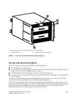
1. Connect the two AC power cords to the two power supplies.

2. Connect the power cords to a power source with voltage of 200 to 240 VAC, 47 to 63 Hz or optionally to a power 

source with voltage of 110 to 120 VAC, 47 to 63 Hz. If using any application blades in the chassis, the 200 to 
240 VAC option is necessary in order to achieve power supply redundancy.

ATTENTION

Use of the high-voltage line (200 to 240 VAC) is highly recommended because of better power-conversion 
efficiency. 
For a fully-loaded DCX 8510-4 or DCX-4S, 200 to 240 VAC is required for high availability (ability to hot swap a 
failed power supply without affecting system operation.

3. Turn the AC power switches on the power supplies to 

I

. The AC power switches light green when switched on and 

power is supplied.

4. The Brocade DCX 8510-4 performs a power-on self-test (POST) each time it is powered on. POST takes 

approximately 10 minutes and is complete when the indicator light activity displays the operational state.

You can bypass POST by using the fastBoot command. You can also disable POST for successive reboots on the 
Brocade DCX 8510-4 using the diagDisablePost command.

ATTENTION

Do not connect the switch to the network until the IP addresses are configured.

Managing cables

The vertical cable management fingers are attached to the rack to either side of the chassis door and allow for 
simple cable management. The fingers can be installed without service disruption.

Route the cables along the front of the blades to keep LEDs visible. Leave at least one meter of slack for each fiber 
optic cable to provide room to remove and replace blades.

ATTENTION

The minimum bend radius for a 50 micron cable is 2 in. under full tensile load and 1.2 in. with no tensile load. 

Cables can be organized and managed in a variety of ways, for example, using cable channels on the sides of the 
cabinet or patch panels to minimize cable management. Following is a list of recommendations:

NOTE

You should not use tie wraps with optical cables because they are easily overtightened and can damage the optic 
fibers.

Plan for rack space required for cable management before installing the switch.

Leave at least 1 m (3.28 ft) of slack for each port cable. This provides room to remove and replace the 
switch, allows for inadvertent movement of the rack, and helps prevent the cables from being bent to less 
than the minimum bend radius.

If you are using Brocade ISL Trunking, consider grouping cables by trunking groups. The cables used in 
trunking groups must meet specific requirements, as described in the 

Fabric OS Administrator’s Guide

.

For easier maintenance, label the fiber optic cables and record the devices to which they are connected.

Keep LEDs visible by routing port cables and other cables away from the LEDs.

Use Velcro

®

 type straps to secure and organize fiber optic cables.

Содержание DCX 8510-4

Страница 1: ...53 1002178 01 53 1002178 01 53 1002178 01 29 April 2011 Brocade DCX 8510 4 Backbone QuickStart Guide...

Страница 2: ...ss cost liability or damages arising from the information contained in this book or the computer programs that accompany it The product described by this document may contain open source software cove...

Страница 3: ...de DCX 8510 4 as a standalone unit quickly Note the following additional documentation For detailed installation and configuration instructions refer to the Brocade DCX 8510 4 Backbone Hardware Refere...

Страница 4: ...s Danger notices A danger notice calls attention to a situation that is potentially lethal or extremely hazardous to people A lightning bolt symbol accompanies a danger notice to represent a dangerous...

Страница 5: ...art Guide 5 of 24 Publication Number 53 1002178 01 FIGURE 1 Port side of the Brocade DCX 8510 4 sample configuration 1 FC16 48 port blade example 4x 3 Control processor blade CP8 2x 2 Core switch blad...

Страница 6: ...n Number 53 1002178 01 FIGURE 2 Port side of the Brocade DCX 8510 4 with the port side exhaust kit installed sample configuration Brocade DCX 8510 4 nonport side The following figure shows a sample co...

Страница 7: ...using the Mid Mount Rack Kit available from your Brocade DCX 8510 4 supplier This chapter describes how to set up the Brocade DCX 8510 4 as a standalone unit For rack mount installation instructions r...

Страница 8: ...allation Procedure Brocade DCX 8510 4 DCX 4S Mid Mount Rack Kit Installation Procedure or Brocade DCX 8510 4 DCX 4S Rack Kit Installation Procedure Mounting and securing Brocade DCX 8510 4 in rack 30...

Страница 9: ...s nameplate Location close to the chassis and easily accessible Grounded outlets installed by a licensed electrician and compatible with the power cords ATTENTION To maximize fault tolerance connect e...

Страница 10: ...ining the following items Brocade DCX 8510 4 Backbone QuickStart Guide Brocade Documentation CD contains documents related to the Brocade DCX 8510 4 ESD grounding strap USB device RS 232 serial cable...

Страница 11: ...area Doorways must be wider than 36 in 91 cm to accommodate the chassis 3 Remove the Brocade DCX 8510 4 port side exhaust kit if ordered accessory kit packing foam and antistatic plastic from the cha...

Страница 12: ...ement fingers are attached to the rack to either side of the chassis door and allow for simple cable management The fingers can be installed without service disruption Route the cables along the front...

Страница 13: ...gh density cabling The FC8 64 high density port blade cannot use the standard LC cables because the pitch between optics in the new mini SFP mSFP transceiver is smaller than in standard SFPs Patch cab...

Страница 14: ...TE For the Brocade 8510 Backbones an off the shelf QSFP cable up to 50 meters long can be used as an ICL cable ATTENTION For the 8510 series models if the QSFP cables are not used make sure the rubber...

Страница 15: ...lly blinks amber after installation then displays steady amber 2 Grasp the QSFP cable by the rubber housing and push it into the QSFP transceiver until it is firmly seated The cable housing is keyed t...

Страница 16: ...mplete the following steps 1 Verify that the Brocade DCX 8510 4 is powered on and that POST is complete by verifying that all power LED indicators on the port control processor and core switch blades...

Страница 17: ...prompt tip dev ttyb 9600 If ttyb is already in use use ttya instead and enter the following string at the prompt tip dev ttya 9600 When the terminal emulator application stops reporting information pr...

Страница 18: ...nfiguration 10 77 77 74 CP1 the CP blade in slot 7 at the time of configuration ATTENTION Resetting an IP address while the Brocade DCX 8510 4 has active IP traffic or has management and monitoring to...

Страница 19: ...connect the active CP blade to the local area network LAN By establishing an Ethernet connection you can complete the Brocade DCX 8510 4 configuration using either a serial session Telnet or manageme...

Страница 20: ...admin chassisname DCX8510_chassis Committing configuration Done 2 Enter chassisName by itself to show the name switch admin chassisname DCX8510_chassis 3 Record the new name for reference Setting the...

Страница 21: ...8 ports The ports and cables used in trunking groups must meet specific requirements Refer to the Fabric OS Administrator s Guide 2 Position one of the optical transceivers so that the key is oriented...

Страница 22: ...ed in slot 3 Some detials for the 8510 8 will be different but the reported information for the QSFPs will be similar Note that the State reported for an unconnected QSFP shown QSFP 0 and Ports 0 3 be...

Страница 23: ...ermine which licenses are enabled use the licenseShow command swDir admin licenseshow AAbbccDDeeFFeeGG Web license Zoning license Extended Fabric license Fabric Watch license Performance Monitor licen...

Страница 24: ...the configupload command This command uploads the Brocade DCX 8510 4 configuration 6 You can run the following commands to see additional configuration information that you can copy to a file to save...

Отзывы: