Broadcom
P411W-32P-UG104
11
P411W-32P PCIe 4.0
User Guide
NVMe Switch Adapter
6 Connector Physical-to-Logical Mapping
The following table shows the adapter's physical connector to logical connector mapping as viewed from the UART interface,
when used with the
bpview
CLI command. The adapter uses x8 SFF-8654 connectors. Each connector is segregated into
quads and mapped accordingly.
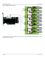
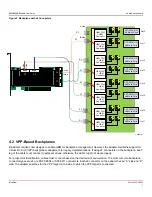
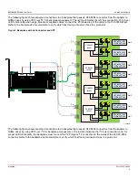
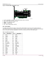
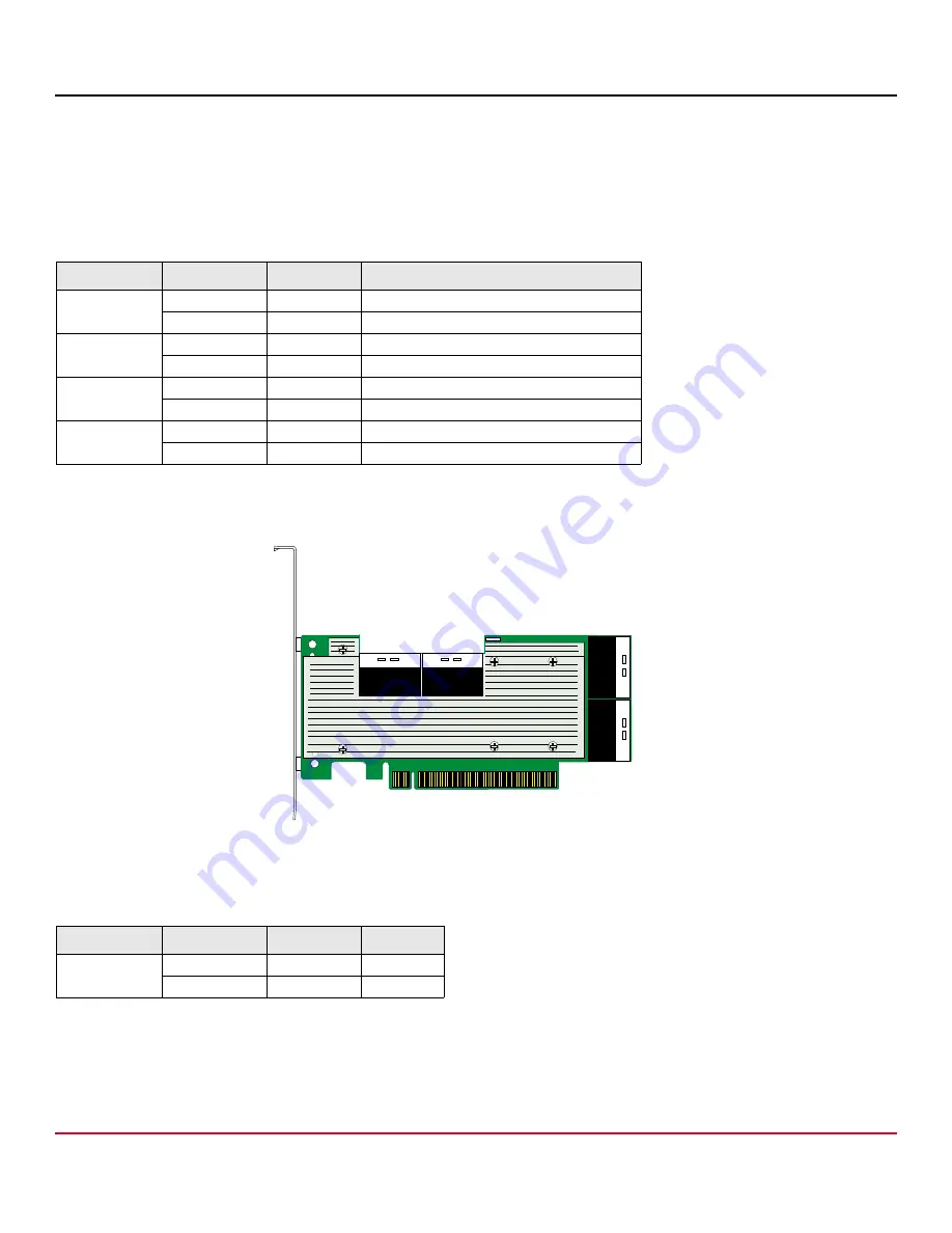
The following figure shows how the connectors are mapped.
Figure 5 Connector Mapping
Each connected drive is a port. For example, if two x4 NVMe drives connect to C0, one drive is on port 0 and the second
drive is on port 4, as shown in the following table.
Use the same numbering schema if you use drives of varying lanes. The following table uses C0 as an example for when a
1-lane drive or 2-lane drive is connected.
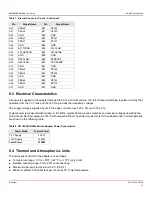
Table 3 Physical Connector-to-Logical Connector Mapping
Adapter Label
Tool Mapping Port Number
PEX88048 Switch Lowest Lane Number
C0
C0.1
0
0
C0.0
4
4
C1
C1.1
8
8
C1.0
12
12
C2
C2.1
32
32
C2.0
36
36
C3
C3.1
40
40
C3.0
44
44
Table 4 x4 Drive-to-Port Connection Example
Adapter Label
Tool Mapping Port Number
Drive
C0
C0.1
0
x4
C0.0
4
x4
#
#
#
#
#
#
#
#
#
#
#
#
?

