G730-Install-IG100 Installation Guide
Brocade
®
G730 Switch Hardware Installation Guide
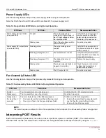
Power Supply LEDs
Use the following table to interpret the power supply LEDs during normal operation.
Note that if both the AC and DC status LEDs are black/off, the power supply is off.
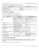
Table 14: Nonport-Side LED Patterns during Normal Operation
LED Name
LED Color
Hardware Status
Recommended Action
No light
The power supply is not
receiving AC input voltage, or
the AC input voltage is below
the operational limit.
Verify that the power supply is
properly seated and that the
power cord is connected to a
functioning AC power source.
Power supply AC input status
(one green LED)
Steady green
The AC input voltage is within
operational range.
No action is required.
Flashing yellow
The output voltage is not
enabled.
Verify that the power supply is
fully seated and that the captive
screw is secured.
Flashing yellow/green (2:1)
The temperature is too hot.
Verify that ambient temperature
is less than 40°C, and check for
intake airflow blockage.
Flashing yellow/green (1:1)
The internal fan is out of
regulation.
Replace the power supply.
Steady yellow
The power supply is faulty or not
plugged in completely.
Check the power cord, current,
voltage, and temperature to
determine the problem.
Power supply DC output status
(one bicolor LED)
Steady green
The DC output is OK.
No action is required.
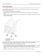
Fan Assembly Status LED
Use the following table to interpret the fan assembly status LED during normal operation.
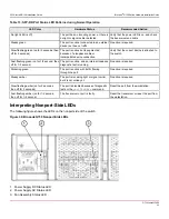
Table 15: Fan Assembly Status LED Patterns During Normal Operation
LED Color
Description
Recommended Action
No light
The fan assembly is not receiving power.
Verify that the fan FRU is seated correctly.
Steady green
The fan assembly is operating normally.
No action is required.
Steady amber
(for more than 5
seconds)
The fan is faulty for one of the following reasons:
•
A fan assembly with mismatched airflow is present.
•
One or more fans in the fan assembly have failed.
Perform one of the following actions:
•
Replace the mismatched fan assembly with
one that has the correct airflow direction.
•
Replace the faulty fan assembly.
NOTE
The switch requires a minimum of two fan assemblies to be functional. One fan assembly failure is supported.
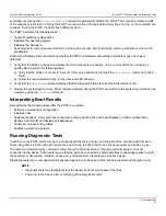
Interpreting POST Results
Each time the switch is powered on, rebooted, or reset, it performs a power-on self-test (POST). The total boot time
with the POST can take several minutes. The POST can be bypassed after subsequent reboots by using the
fastboot
G730-Install-IG100
64
Содержание Brocade G730
Страница 94: ......

