Precautions specific to the fan assemblies
CAUTION
Disassembling any part of the power supply and fan assembly voids the warranty and regulatory certifications. There are no
user-serviceable parts inside the power supply and fan assembly.
CAUTION
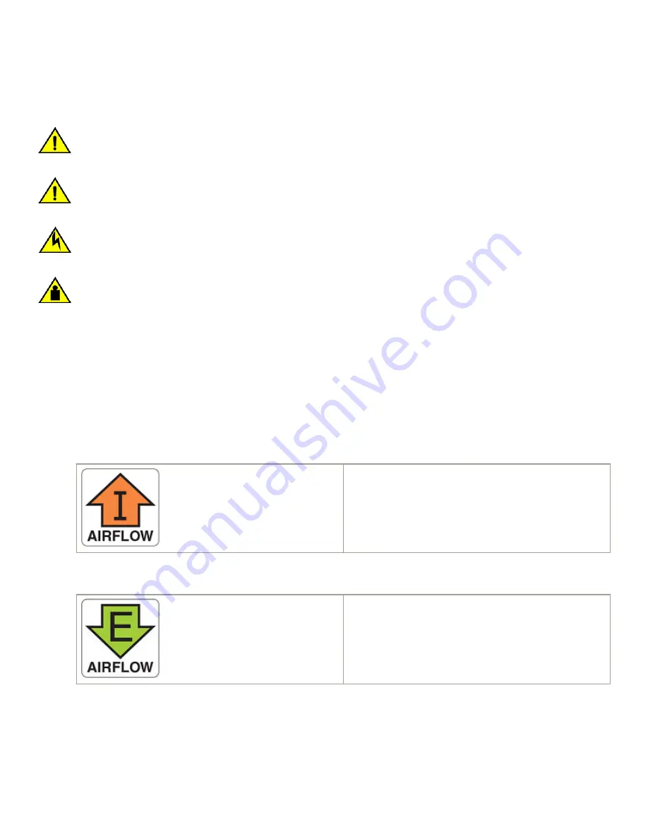
Ensure that the airflow direction of the power supply unit matches that of the installed fan tray. The power supplies and fan
trays are clearly labeled with either a green arrow with an "E", or an orange arrow with an "I."
CAUTION
If you do not install a module or a power supply in a slot, you must keep the slot filler panel in place. If you run the chassis
with an uncovered slot, the system will overheat.
CAUTION
To prevent damage to the chassis and components, never attempt to lift the chassis using the fan or power supply handles.
These handles were not designed to support the weight of the chassis.
NOTE
The equipment installation must meet NEC/CEC code requirements. Consult local authorities for regulations.
Identifying the airflow direction
The power supply and fan assemblies are identified by the following airflow directions:
•
Intake power supply and fan assembly with an orange "I" label or without any label
: Pulls air from the nonport-side of the
switch and exhausts it out the port side.
–
Nonport-side air intake
–
Port-side air exhaust
–
Back-to-front (nonport-side to port-side) airflow
–
Part numbers ending with
-R
•
Exhaust power supply and fan assembly with a green "E" label
: Pulls air from the port side of the switch and exhausts it out
the nonport-side.
–
Nonport-side air exhaust
–
Port-side air intake
–
Front-to-back (port-side to nonport-side) airflow
–
Part numbers ending with
-F
Fan assembly status LED
Refer to the following table to interpret the fan assembly status LED during normal operation
Fan assembly status LED
Brocade G630 Hardware Installation Guide
53-1005235-02
83
Содержание Brocade G630
Страница 1: ...HARDWARE INSTALLATION GUIDE Brocade G630 Hardware Installation Guide 53 1005235 02 29 December 2017 ...
Страница 10: ...Brocade G630 Hardware Installation Guide 10 53 1005235 02 ...
Страница 22: ...Brocade G630 Hardware Installation Guide 22 53 1005235 02 ...
Страница 48: ...Brocade G630 Hardware Installation Guide 48 53 1005235 02 ...
Страница 72: ...Brocade G630 Hardware Installation Guide 72 53 1005235 02 ...
Страница 88: ...Brocade G630 Hardware Installation Guide 88 53 1005235 02 ...
Страница 96: ...Brocade G630 Hardware Installation Guide 96 53 1005235 02 ...
Страница 100: ...Brocade G630 Hardware Installation Guide 100 53 1005235 02 ...


