==================================================================================================
x4
34
2
34
2
2
20
20
7
7
34
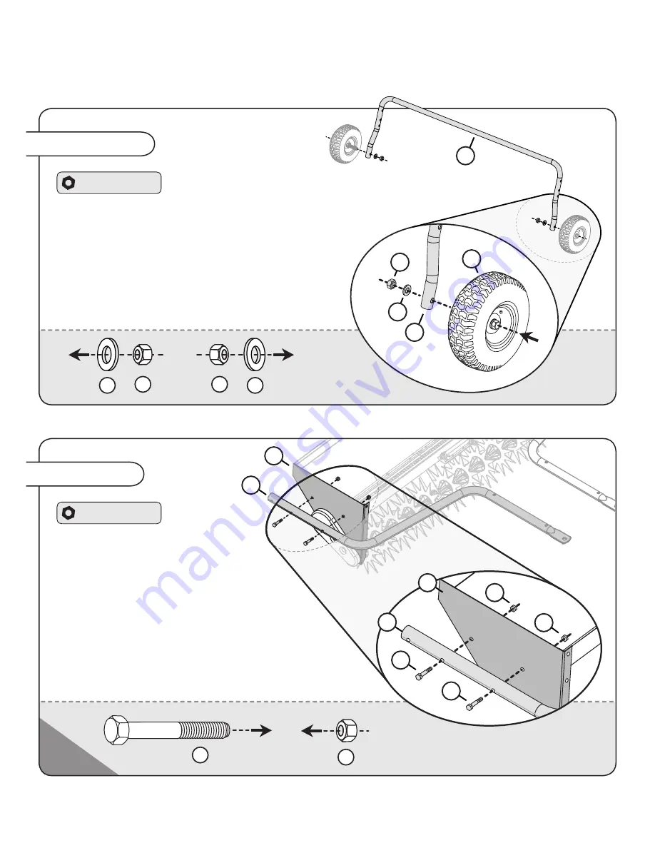
Assembly Step 2
Hardware Panel 2
1. Align one of the tow bars (
20
) with
the small, side panels of the hopper
assembly (
7
) as illustrated.
2. From the outside edge of the hopper, run
two 5/16 x 2” hex bolts (
34
) through the tow
bar and hopper assembly (
7
).
3. Tightly secure each bolt (
34
) in place with a
5/16” lock nut (
2
).
4.
Repeat this step on the other side of the hopper with
the additional tow bar and hardware provided.
Assembly Step 1-B
Hardware Panel 1
45
47
45
47
1. Add a wheel (28) from Step 1-A to the support assembly (21).
NOTE: Run each bolt from the outside, through the holes at the
base of the assembly as illustrated.
2. Add one 1/2” flat washer (
47
) to the 1/2 x 3-1/2” hex
head bolt (
32
).
3. Tightly secure in place with one 1/2” lock nut (
45
).
Repeat this step with the other wheel as illustrated.
47
21
21
28
45
ASSEMBLY
English Manual
8
1018947-C


