7
GB
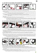
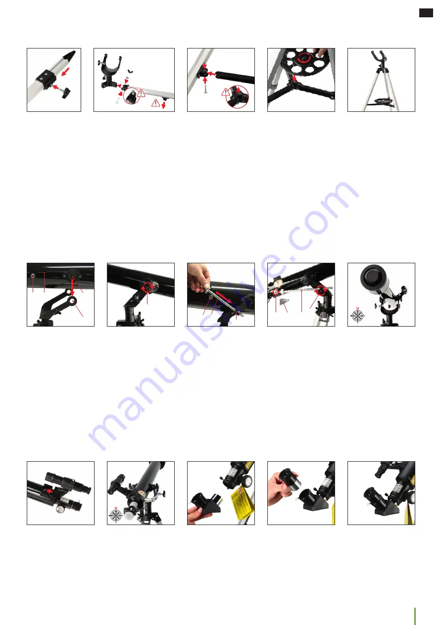
A | SETTING UP THE TRIPOD AND MOUNTING THE ACCESSORY TRAY
4
4
TOP
1) Screw the three wing screws (23) into the threads of the tripod leg clamps (22) and tighten them hand-tight.
2) Slide the mounting forks (18) of the three tripod legs onto the mounting shafts (32) and attach them to the mounting pins (30) with the
fastening screws (17).
IMPORTANT: When mounting, make sure that the mounting pins (24) point downwards and the head of the hexagon head screw
(17A) engages in the corresponding recess on the mounting fork.
3) Remove the small mounting screws (25) from the ends of the tripod spider (26) and set them aside within reach. Place the ends of the
tripod spider (26) on the mounting pins (24) and fasten them with the fastening screws previously removed.
IMPORTANT: Make sure that the central thread (26B) of the tripod spider points upwards in the direction of the mounting fork (30)
when mounting.
4) Place the tripod upright on a firm, preferably level surface so that it is horizontal and secure. Screw the accessory tray (27) into the central
thread (26B).
5) The base of the telescope with tripod, mount and accessory tray is now ready for use.
NOTE: The foot tips of the tripod legs can compensate for slight unevenness of the ground. For more uneven surfaces, the heights
of the tripod legs can be adjusted independently. To do this, loosen the wing screws (23) on the tripod leg clamps (22) slightly
and pull the lower tripod leg parts further apart or push them in accordingly. Then hand-tighten the wing screws (23) again.
To check a level stand, place a spirit level on the accessory tray.
B | FASTENING THE TELESCOPE IN THE MOUNT AND ALIGNING IT
X
X
A
A
A
I
ATTENTION! Always hold the tube with one hand during the following assembly steps to prevent it from falling or turning over. This
can lead to irreparable damage to the tube and optics!
6) Keep the fixing screws (4), the stabilizing rod (28) and the fixing screw (28A) within reach. Position the optical tube (2) from above in the
mounting fork so that the internal threads (2A) on the optical tube (2) are located exactly behind the openings (30A) of the mounting fork.
7) Take the fixing screws (4) and screw them through the openings (30A) of the mounting fork into the internal threads (2A) on the optical
tube and tighten them hand-tight.
8) Take the stabilizing rod (28) and push it through the locating hole of the fixing screw (29) and tighten the fixing screw slightly.
9) Screw the stabilization rod hand-tight to the internal thread (X) of the optical tube (2) using the small fixing screw (28A) and the screwdriver
(I).
10. Loosen the fixing screw (31) for horizontal movement to move the optical tube (2) horizontally (to the right or left). For fixing in a specific
horizontal position, hand-tighten the fixing screw (31). To move the optical tube (2) vertically, slightly loosen the fixing screws (4) for the
optical tube (2) and the fixing screw (29) on the mounting fork. After reaching the desired position, hand-tighten all fixing screws again.
NOTE: Before each night observation, the optical tube (2) should be aligned horizontally and with the objective lens (3) facing north.
A small compass can help with accurate alignment.
C | ATTACHING ACCESSORIES FOR VISUAL OBSERVATION
4
4
4
4
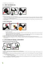
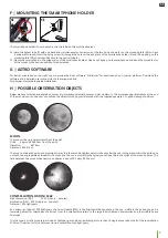
BASIC ACCESSORIES - VIEWFINDER, DIAGONAL MIRROR AND EYEPIECES
11) Insert the viewfinder (6) with the viewfinder bracket (6a) into the viewfinder shoe (7) on the optical tube (2).
12) The viewfinder (6) is correctly mounted when the objective lens (3) and the viewfinder lens (5) point in the same direction.
13) Loosen the fixing screw (13) on the focuser ring (14) so that the protective cap can be removed and the opening of the eyepiece extension
(15) is not blocked. Insert the diagonal mirror (12) into the eyepiece extension (15) and hand-tighten the fixing screw (13) on the focuser
ring (14) again.
14) Loosen the fixing screw (11) on the diagonal mirror (12) so that its opening is not blocked. Insert an eyepiece (10) into the diagonal mirror
(12) and hand-tighten the fixing screw (11) on the diagonal mirror (12) again.
TIP! Start each observation with a low magnification eyepiece. The following applies to this: The larger the focal length in mm, the
lower the magnification. Example: a 10mm eyepiece provides less magnification than a 4mm eyepiece
Содержание 9618761000000
Страница 1: ...SKYLUX 60 700 AZ Refractor telescope with azimuthal mount Art No 9618761000000 GB INSTRUCTION MANUAL...
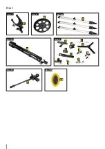
Страница 2: ...2 FIG 1 Box I Box II Box III Box IV Box VI Box VII Box V A B C D E O N G H M F J K Q L I P...
Страница 3: ...3 GB FIG 2 B C A A A B A B A B A A...
Страница 13: ...13 GB...
Страница 14: ...14...
Страница 15: ...15 GB...


