UMPCEC
Rev 3.0, 6/2012
User Manual
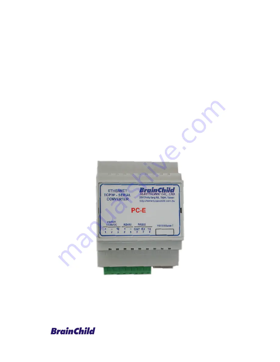
Protocol Converter
PC-E, Serial to Ethernet (RS232/485 Modbus RTU to Modbus TCP/IP)
Страница 1: ...UMPCEC Rev 3 0 6 2012 User Manual Protocol Converter PC E Serial to Ethernet RS232 485 Modbus RTU to Modbus TCP IP...
Страница 2: ...ied and is not due to customer abuse or the other exceptions described with product warranty Brainchild Electronics will at its option repair or replace the Product returned to it freight prepaid whic...
Страница 3: ...e factory for service information or repair Any Mechanical or Electrical Modification to this Unit will void All Warranties DISCLAIMER Information contained herein is subject to change without notice...
Страница 4: ...cification 9 5 Wiring 9 6 Configuration 10 6 1 Power Connections 10 6 2 Ethernet Connection 10 6 3 Indication LED S 10 6 4 Connecting to a PC which is not Connected to a Network 11 6 5 Connecting to a...
Страница 5: ...ach RS485 network is separate it is possible to have repeated Modbus ID s on the RS485 networks The IP address differentiates between the different RS485 networks Consequently many hundreds of IO modu...
Страница 6: ...ured to use Port 1234 This port number informs the converter that any data that is received in a UDP datagram must be transmitted out the serial port without any protocol conversion Modbus Master PLC...
Страница 7: ...et implementation waits for messages to come in on the Ethernet network and sends them out the serial port Any messages being received on the serial port are sent out on the Ethernet network As there...
Страница 8: ...noise into both power and signal lines as well as direct radiation into the module causing negative effects on the system Appropriate grounding shielding and other protective steps should be taken at...
Страница 9: ...ata Bits 5 6 7 8 Parity None Even Odd Serial Stop Bits 1 2 Operating Temperature 10 C to 50 C Temperature Storage Temperature 40 C to 85 C Connectors Power and Comms 8 way screw connector Humidity Up...
Страница 10: ...d to terminal 1 12 24VDC and terminal 2 0V The power LED will illuminate and all LED s will be off 6 2 Ethernet Connection Next the Ethernet connection is required either through a network or directly...
Страница 11: ...ct connection between the PC and the Protocol converter a crossover Ethernet cable is required To setup your PC to connect directly to the Protocol converter PC E an IP address in the same range as th...
Страница 12: ...ny hub belonging to the network Please note that PC E is shipped with default IP address of 192 168 0 112 To connect PC E with existing network first IP address of PC E should be changed to free IP ad...
Страница 13: ...be run from the command line or from a DOS prompt on the PC as follows Open the Windows Start Menu Click Run In the Open box type ping 192 168 0 112 If the network connection is OK between PC and Prot...
Страница 14: ...uch as Internet Explorer or Netscape is needed To view the default Web page in Protocol converter start the Web browser and type 192 168 0 112 into the address line of the browser window The main page...
Страница 15: ...shipped with a default IP address of 192 168 0 112 the PC can be setup with an IP address of 192 168 0 113 2 Does the Protocol converter respond to PING requests Yes The PC and Protocol converter are...
Страница 16: ...ctive after the Protocol converter power has been switched off and on again This feature allows you to check that the correct IP address has been entered before being activated If the IP address has b...
Страница 17: ...it can be used again This timer is triggered by activity on the converter so if there is no communications activity for longer than the timeout period the socket will close Converter Mode These modes...
Страница 18: ...out will expire and allow the converter to look for the next TCP message This timeout must be longer than the turn around time of the slave device or it will timeout before the slave replies This time...
Страница 19: ...the modules be connected together For modules that are far apart a second twisted pair should be used as the 0V link On the PC E terminal 6 GND is used as the 0V connection In certain applications whe...
Страница 20: ...20 If J5 is setup as shown below with J5A 2 3 and J5B 1 2 then a 120ohm active termination with Low Line Idle will be connected to the RS485 network...
Страница 21: ...product Product Name Protocol Converter Serial to Ethernet Model Number s PC E complies with EMC Directive 89 336 EEC and Low Voltage Equipment Directive 73 23 EEC and conforms to the following Produc...
Страница 22: ...t Ethernet cable between PC E to PC 3 Using web browser like internet explorer type http 192 168 0 112 ip htm Now you can access PC E configuration via web server If you are unable to access PC E web...
Страница 23: ...ontrollers Make sure that address in RS485 is unique BTC 4100 Controller Address 1 Baud rate 9600 bps Data bits 8 Stop bits 1 Parity None 7 Now type http 192 168 0 30 ip htm in web browser and configu...
Страница 24: ...24 Enter submit button after entering settings as above 8 Then restart power supply to PC E converter 9 If you are using BTC 4100 then check Modbus address for Set point SP and Process value PV...
Страница 25: ...25 10 Now if you are using DAQ software do the following steps Create a new project Click at No Make sure bank1 is configured for Modbus_TCP...
Страница 26: ...Enter Bank 1 Make sure bank is configured for Modbus TCP Enter tag name PV1 Select Use Gateway Device Node address Select address of controller This is very important Enter IP address 192 168 0 30 Re...
Страница 27: ...ck Node IP details It shows address of controller and IP address of PC E Now click at Save icon then click at Return icon Check Scan time and sampling rate at bottom side of screen Scan time is more t...
Страница 28: ...n tab then adjust sampling rate and time out Then check again 11 Now similarly add other tags like Set point SP1 etc 8 2 IO modules to DAQ software via PC E Sample Note Max 127 IO modules can be conne...
Страница 29: ...from default 192 168 0 112 to another IP address say 192 168 0 30 Then click at submit button Restart the power supply to PC E converter 5 Now using Ping instruction check if there is good communicat...
Страница 30: ...30...
Страница 31: ...utton after entering settings as above 8 Then restart power supply to PC E converter 9 If you are using DAQ software do the following steps Create a new project Click at No Make sure bank1 is configur...
Страница 32: ...32 If all wiring and configurations are correct IO module data base will be added into DAQ software automatically If there is error it requires to re check the following...
Страница 33: ...on then click at Return icon Click at Yes Then it will show temperature values of IO 6RTD module Check Scan time and sampling rate at bottom side of screen Scan time is more than sampling rate then it...
Страница 34: ...34 Click at option icon Select Communication tab then adjust sampling rate and time out Then check again...