


Commissioning
6 720 808 928 (2017/06)
33
6.5
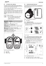
Control valve status indication
The control valves for Central Heating and Domestic Hot Water have
three indicators on the head of the actuator to denote operational states,
see figure 7, items [4] and [5] to locate the valves.
The case, insulation and control box will need to be removed to gain
access to the control valve indicators.
There are three symbols on the head of the valve actuator, behind these
symbols are coloured indicators that are used to indicate the position of
the plunger or a possible error situation (error indication
9.4). The
table below gives operational details of the coloured indicators and their
meaning:
Fig. 44 Control valve status indicators
[1]
Circle - Green
[2]
Square - Blue
[3]
Triangle - Orange
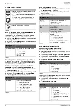
6.6
Central heating circulation pump
The circulating pump has five LED indicators [1], this shows details of
operational status, current pump curve setting, adjusting pump curve
setting and fault indication.
Fig. 45 Circulating pump status indication
[1]
LED indicators
6.6.1
Pump key lock function
The key lock function prevents the adjustment of the pump settings.
▶ To toggle the key lock function press and hold the button for
approximately 10 seconds.
Fig. 46 Key lock
6.6.2
Pump operational status and view pump curve setting
The pump displays the current operating status [1] during normal
running. It can also display the current pump curve setting [2].
▶ Press the button on the pump to view the current pump curve setting.
– The default pump curve setting is PP3, highest proportional
pressure curve.
After approximately 2 seconds the LED indicators will return to
current operational status display mode.
Fig. 47 Operation and view setting
[1]
Normal operation indication (
table 13 for details)
[2]
View setting (current pump curve setting,
table 15 for details)
LED power save mode
▶ During normal operation if the valve has not moved
from its current position for approximately 15
seconds it will enter a power save mode and the
active LEDs will turn off.
Indicators ON
Description
Orange, blue
and green
• Valve in start up mode, will not respond to any
input.
• Valve re-calibration is running.
Green
Valve is completely open
Green and blue
Valve is between 60 and 99.9% open, but not fully
open
Blue
Valve is between 40 and 60% open
Blue and orange Valve is between 0.1 and 40% open, but is not
completely closed
Orange Valve
is
completely closed
Table 12 Control valve operation status
6720808928-30.1W
o
3
2
1
1
2
3
4
5
6720808917-23.1W
o
1
6720808917-25.1W
o
>10 s
>10 s
6720808917-26.1Wo
≈
2 s
≈
10 s
≈
2 ss
>2 s
1
2
Содержание Worcester Greenstar HIU
Страница 65: ...6 720 808 928 2017 06 65 Notes ...
Страница 66: ...6 720 808 928 2017 06 66 Notes ...
Страница 67: ...6 720 808 928 2017 06 67 Notes ...