68
en | Installation
UHI/UHO Series
F.01U.167.418 | 3.0 | 2010.04
Installation Manual
Bosch Security Systems, Inc.
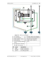
Drawing layout and installation wiring diagram is in accordance
with the NEC, ANSI/NFPA 70 for indicating recommended
locations and wiring methods.
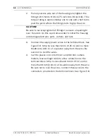
5.
On heater and heater/blower units, make sure the heater
and fan wires stay connected to the terminal block.
6.
Make sure the BNC cable is separated from the Mains
power and heater.
5.8
Video coax connection
See
Table 4.3
and
Table 4.4
for UHO-HBPS-10, UHO-HPS-50 and
UHO-HBPS-50 models.
1.
Install a 1/2-inch NPT fitting into the available hole in the
rear cap.
2.
Route the video coax cable through one of the fittings
installed in
Step 1
, or one of the feed-through fittings in the
base.
3.
Attach the BNC connector to the coax and connect it to the
camera.
CAUTION!
For security protection of the device, the branch circuit
protection must be secured with a maximum fuse rating of 16A.
This must be in accordance with NEC 800 (CEC Section 60).
CAUTION!
Use only cables meeting specifications in
Section 5.3 Cable
requirements
for wiring video coax connections.
CAUTION!
Always securely tighten all fittings to ensure a liquid-tight seal.
Failure to do so could allow water to enter the housing and
damage the camera and lens. If a sealant is used, be sure it is a
neutral cure type. Sealants that release acetic acid may harm
camera electronics. Use of drip loops is recommended on the
wiring outside of the rear end cap.
Содержание UHI Series
Страница 2: ......
Страница 213: ...UHx シリーズハウジング 分解組立図 ja 213 Bosch Security Systems Inc ユーザーマニュアル F 01U 167 418 2 0 2010 03 9 分解組立図 図 9 1 分解組立図 ...
Страница 327: ......
Страница 328: ...Bosch Security Systems Inc www boschsecurity com Bosch Security Systems Inc 2010 ...

