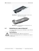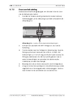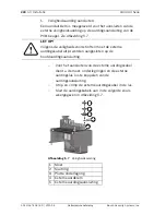
background image

248

nl | UHO-HBPS-10, -50, en UHO-HPS-50

UHI/UHO Serie

F.01U.167.418 | 3.0 | 2010.04

Gebruikershandleiding

Bosch Security Systems, Inc.

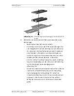
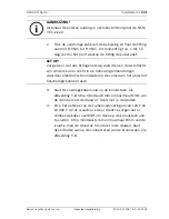
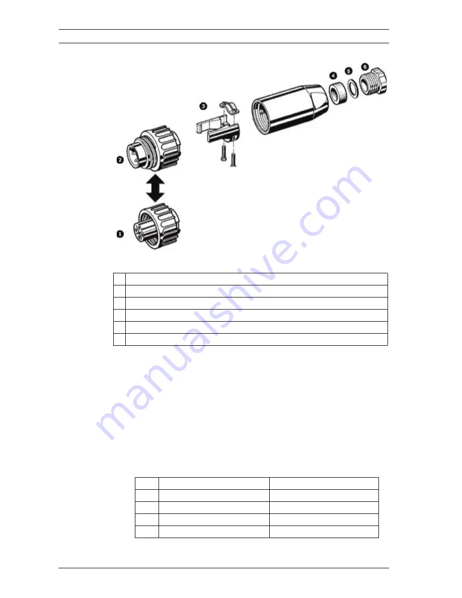
Afbeelding 6.1

4-pins koppelstekkereenheid

3.

Op de kroonsteen die in deze camera's is aangebracht, 

kunnen kabels met een diameter van 0,5 mm

2

 tot 2,5 mm

2


(20 tot 14 AWG) worden aangesloten. Bij het gebruik van 

kabels met een grotere diameter dient u deze aan het 

uiteinde (voor aansluiting op de kroonsteen) in draden met 

kleine diameters te splitsen.

4.

Sluit de kabel voor de voedingsingang aan op de 

schroefaansluitingen van de meegeleverde koppelstekker. 

Zie 

Afbeelding 6.1

 en 

Tabel 6.1

.

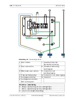
Tabel 6.1

4-pins kabelaansluitingen

1 UITSLUITEND 230 V AC! Vrouwelijke klemring
2 UITSLUITEND 24 V AC! Mannelijke klemring
3 Ingebouwde trekontlaster
4 Afdichtende pakking
5 Metalen onderlegring
6 Kabelmoer

Pin

Functie

Draadkleur kabelboom

1

AC neutraal

Blauw

2

AC onder spanning

Bruin

3

Geen aansluiting

Niet gebruiken

4

Aarding

Groen/geel

Содержание UHI Series

Страница 1: ...ies UHI UHO Series de Benutzerhandbuch en Installation Manual es Manual del usuario fr Manuel d utilisation it Manuale utente ja ユーザーマニュアル nl Gebruikershandleiding pl Instrukcja instalacji pt Manual do utilizador ...

Страница 2: ......

Страница 3: ...rhandbuch 4 en Installation Manual 41 es Manual del usuario 76 fr Manuel d utilisation 114 it Manuale utente 152 ja ユーザーマニュアル 189 nl Gebruikershandleiding 215 pl Instrukcja instalacji 252 pt Manual do utilizador 290 ...

Страница 4: ...Werkzeuge 20 5 2 Kameraanforderungen 20 5 3 Kabelanforderungen 21 5 3 1 Videoübertragung Koax 21 5 3 2 Netzkabel 21 5 3 3 Kabel für Objektivsteuerung 22 5 4 Gehäusemontage 22 5 5 Öffnen der Abdeckung 23 5 6 Installieren von Kamera Objektiv 24 5 7 Anschließen von Kamera Objektiv 26 5 7 1 Halterungen 26 5 7 2 Kabelkanal 26 5 7 3 Kabeldurchführung 27 5 7 4 Netzstromanschlüsse 28 5 8 Videokoaxverbindu...

Страница 5: ...is de 5 Bosch Secuurity Systems Inc Benutzerhandbuc F 01U 167 418 v3 0 2010 04 6 UHO HBPS 10 50 und UHO HPS 50 36 6 1 Anschließen von Kamera Objektiv 36 6 2 Videokoaxverbindung 38 7 Betrieb 38 8 Wartung 38 9 Explosionsdarstellung 39 ...

Страница 6: ...eräten Öfen oder anderen Geräten einschließlich Verstärkern die Wärme erzeugen 3 Belüftung Sofern vorhanden dienen Öffnungen im Gehäuse der Belüftung um eine Überhitzung zu verhindern und einen verlässlichen Betrieb des Geräts sicherzustellen Diese Öffnungen dürfen nicht blockiert oder verdeckt werden Bauen Sie das Gerät nur dann in ein Gehäuse ein wenn für angemessene Belüftung gesorgt ist oder d...

Страница 7: ... ein Durch falsche Einstellung anderer Bedienelemente kann das Gerät beschädigt werden Durch Verwendung von Bedienelementen oder Einstellungen sowie Durchführung von Verfahren die nicht in der Betriebsanleitung angegeben sind kann es zum Austritt gefährlicher Strahlung kommen 8 Überlastung Überlasten Sie Steckdosen und Verlängerungskabel nicht Dies kann zu Feuer oder einem elektrischen Schlag führ...

Страница 8: ...eltenden Vorschriften für elektrische Anlagen Leistungsstufe 2 entsprechen Die Stromquelle darf nicht an den Anschlüssen bzw an den Stromversorgungsanschlüssen am Gerät geerdet werden Wenn Sie sich nicht sicher sind ob Sie das Gerät mit einer bestimmten Stromquelle betreiben können fragen Sie den Händler bei dem Sie das Gerät erworben haben oder Ihren Stromanbieter 11 Wartung Versuchen Sie nicht d...

Страница 9: ...rischen Schlag oder anderen Gefahren führen 14 Sicherheitstest Sicherheitstests müssen nach der Wartung oder Instandsetzung des Geräts durchgeführt werden um den ordnungsgemäßen Betrieb zu gewährleisten 15 Installation Bei der Installation sind die Anweisungen des Herstellers und die jeweils zutreffenden Vorschriften für elektrische Anlagen zu beachten 16 Zubehör und Veränderungen Verwenden Sie nu...

Страница 10: ...ürzen gebracht Befestigen Sie das Gerät entsprechend den Anweisungen vom Hersteller Hauptschalter Die Elektroinstallation des Gebäudes muss einen Hauptschalter mit einem Kontaktabstand von mindestens 3 mm zwischen den einzelnen Polen umfassen Falls das Gehäuse zu Wartungs und oder anderen Zwecken geöffnet werden muss dient dieser Hauptschalter als wichtigste WARNUNG Zeigt eine potenzielle Gefahren...

Страница 11: ...gsgemäß geerdet ist Bevor die Erdungsverbindung über den Schutzkontaktnetzstecker oder die Masseklemme getrennt wird müssen die Eingangsanschlüsse des Geräts von jeglichen Außeninstallationen getrennt werden Wenn an das Gerät Außeninstallationen angeschlossen werden müssen geeignete Sicherheitsvorkehrungen getroffen werden wie z B eine sachgemäße Erdung Nur für in den USA erhältliche Modelle Absch...

Страница 12: ...reisschutz mit einer maximalen Sicherungsbemessung von 16 A abgesichert sein Dies muss gemäß NEC 800 CEC Abschnitt 60 erfolgen Erdung und Polung Dieses Gerät verfügt möglicherweise über einen gepolten Wechselstromstecker einen Stecker bei dem ein Stift breiter ist als der andere Bei dieser Schutzvorrichtung kann der Stecker nur in einer Richtung in eine Steckdose eingesetzt werden Wenn Sie den Ste...

Страница 13: ...n unterbrochen Stromleitungen Die Kamera darf nicht in der Nähe von Überlandleitungen Stromkreisen elektrischer Beleuchtung oder an Standorten an denen sie mit Stromleitungen Stromkreisen oder Beleuchtungskörpern in Berührung kommen kann positioniert werden SELV Alle Ein und Ausgänge sind SELV Kreise Safety Extra Low Voltage SELV Kreise dürfen nur an andere SELV Kreise angeschlossen werden Da die ...

Страница 14: ...nen dieses Produkts UL ÜBERNIMMT WEDER EINE AUSDRÜCKLICHE NOCH EINE STILLSCHWEIGENDE GEWÄHRLEISTUNG ODER ZERTIFIZIERUNG BEZÜGLICH DER LEISTUNG ODER ZUVERLÄSSIGKEIT JEGLICHER SICHERHEITS ODER SIGNALBEZOGENER FUNKTIONEN DIESES PRODUKTS Copyright Dieses Benutzerhandbuch ist geistiges Eigentum von Bosch Security Systems Inc und urheberrechtlich geschützt Alle Rechte vorbehalten Eingetragene Marken All...

Страница 15: ... wurden eingehend geprüft Zum Zeitpunkt der Drucklegung war der Text vollständig und richtig Aufgrund der stetigen Weiterentwicklung der Produkte kann der Inhalt dieses Benutzerhandbuchs ohne Ankündigung geändert werden Bosch Security Systems haftet nicht für Schäden die direkt oder indirekt auf Fehler Unvollständigkeit oder Abweichungen zwischen Benutzerhandbuch und beschriebenem Produkt zurückzu...

Страница 16: ... und Versandanweisungen einzuholen Kundendienstzentralen Europa Naher Osten Afrika Reparaturcenter Telefon 31 0 76 5721500 Fax 31 0 76 5721413 E Mail RMADesk STService nl bosch com Asien Reparaturcenter Telefon 65 63522776 Fax 65 63521776 E Mail rmahelpdesk sg bosch com Garantie und weitere Informationen Wenn Sie allgemeine Fragen oder Fragen zur Garantie haben können Sie sich an Ihren Bosch Secur...

Страница 17: ... 2 Schraube 1 4 20 x 3 4 Zoll SS 2 Schraube 1 4 20 x 5 8 Zoll SS 2 Schraube 1 4 20 x 7 16 Zoll SS 2 Schraube 1 4 20 x 1 2 Zoll SS 3 Schraube manipulationssicher M3 5 T15 1 Schraubenschlüssel manipulationssicher M3 5 T15 1 Kameraeinsatz Teil A PS 1 Kameraklemme SS 2 Große Unterlegscheibe flach zwischen Kamera und Einsatz SS 3 Unterlegscheibe flach M6 SS 3 Sicherungsscheibe M6 SS 3 Unterlegscheibe f...

Страница 18: ...den Karton deshalb auf 3 Service Siehe www boschsecuritysystems com 4 Beschreibung Die Gehäuse der UHI UHO Serie verfügen über ein ansprechendes Design für den Einsatz innerhalb und außerhalb von Gebäuden Diese Gehäuse entsprechen den Kundenanforderungen hinsichtlich Aussehen Kosteneffizienz und einfacher Installation Eine Beschreibung der Modelle für den Inneneinsatz finden Sie in Tabelle 4 1 Hei...

Страница 19: ...62 mm UHO HGS 10 UHO HBGS 10 UHO HBPS 10 Installiertes Zubehör HE SB HE L SB HE L SB 4 polig Spannungsbereich Leistung 21 6 bis 25 4 VAC 40 W Nennspannung der Kamera 24 VAC Max Kamera Objektivgröße HxBxT 91 x 81 x 262 mm UHO HBGS 60 Installiertes Zubehör HE L SB Spannungsbereich Leistung 108 bis 132 VAC 45 W Nennspannung der Kamera 120 V Max Kamera Objektivgröße HxBxT 91 x 81 x 262 mm UHO HGS 50 U...

Страница 20: ...al gemäß den jeweils zutreffenden Elektrovorschriften ausgeführt werden VORSICHT Die ordnungsgemäße und sichere Montage der Geräte muss an einer Tragstruktur erfolgen die das Gewicht des Geräts tragen kann Wählen Sie Halterungen und Schwenk Neigevorrichtungen nicht im Lieferumfang enthalten mit äußerster Sorgfalt aus Das Gewicht der Geräte und die Beschaffenheit der Montageoberfläche müssen ebenfa...

Страница 21: ... 9 mm Kabelform Rund Kabelschirm 93 Kupfergeflecht Innenleiter Mehrdrähtiges Kupfer oder Massivkupfer DC Widerstand RG 59 U RG 11 U 15 Ohm 1000 m 6 Ohm 1000 m Kabelimpedanz 75 Ohm Prüfstelle UL Umgebungsbedingungen Außeneinsatz Temperaturbereich 80 C oder höher Referenztyp Belden 9259 Kabelausführung 3 x 18 AWG Kabeldurchmesser außen 4 6 bis 7 9 mm Kabelform Rund Leiter 3 oder 2 Nennspannung 300 V...

Страница 22: ... 2 Die ganz außen liegenden Öffnungen mit Gewinde 1 4 20 dienen zur Befestigung an Durchführungshalterungen Die ganz innen liegenden Öffnungen mit Gewinde 1 4 20 dienen zur Befestigung an anderen Halterungen und Schwenk Neigevorrichtungen siehe Bild 5 1 Kabelausführung H05RN F 3 G 0 75 H05RN F 3 G 1 00 Kabeldurchmesser außen 4 6 bis 7 9 mm Kabelform Rund Leiter 3 oder 2 Nennspannung 300 V Prüfstel...

Страница 23: ...e die Abdeckung indem Sie die drei Verschlüsse an der Gehäuseseite öffnen siehe Bild 5 2 Falls die optionalen manipulationssicheren Schrauben angebracht sind müssen Sie diese vor dem Öffnen der Verschlüsse mit Hilfe des mitgelieferten Schraubenschlüssels entfernen Bild 5 2 Entriegeln der Abdeckung WARNUNG Das Heizelement wird während des Betriebs HEISS NICHT BERÜHREN Schalten Sie das Heizelement b...

Страница 24: ...alls Sie die Durchführungshalterung verwenden lesen Sie die Informationen in Abschnitt 5 7 3 Kabeldurchführung Seite 27 3 Installation von Kameras mit Zoomobjektiv Befestigen Sie das Objektiv an der Kamera Montieren Sie die Kamera und das Objektiv mit den verschiedenen 1 4 20 Schrauben und geeigneten 4 mm bzw 9 mm Abstandhaltern im Lieferumfang enthalten am Kameraeinsatz Dieser Kameraeinsatz ist b...

Страница 25: ...v mittig im Fenster ausgerichtet ist Befestigen Sie die Kamera und den Abstandhalter mit der 1 4 20 x 5 8 Zoll Schraube und der großen flachen Unterlegscheibe am Kameraeinsatz siehe Bild 5 4 Schieben Sie den Einsatz mit der Kamera und dem Objektiv dann in die Aussparung bei den Gehäusescharnieren siehe Bild 5 3 Schieben Sie die gesamte Baugruppe nach vorne bis ca 5 mm vor das Fenster Stecken Sie d...

Страница 26: ...useabdeckung Die Öffnungen sind für Halterungen für 3 8 Zoll NPT oder 1 2 Zoll NPT Kabelkanäle ausgelegt 2 Alle ungenutzten Öffnungen müssen mit den Schutzkappen versehen werden die mit dem Gehäuse geliefert wurden WARNUNG Verwenden Sie zum Anschließen von Kamera und Objektiv ausschließlich Kabel die den Spezifikationen in Section Kabelanforderungen entsprechen VORSICHT Alle Halterungen müssen ste...

Страница 27: ...uß des Gehäuses 3 Ziehen Sie die Kabel durch die Halterungen in das Gehäuse Ziehen Sie die Halterung mit einem Drehmoment von 4 0 Nm bis 4 5 Nm fest Dieses Drehmoment entspricht etwa 1 bis 1 5 Drehungen nach dem Punkt an dem die Halterung am Kabel zu greifen beginnt Falls Sie die Halterung nicht fest genug anziehen führt dies zu Wasser eintritt und Beschädigung aller elektronischen Teile 4 Montier...

Страница 28: ... 2 5 mm2 AWG 14 wird ein Spleiß für die Verbindung mit dem Anschlussblock benötigt 1 Falls Sie die Installation mit Kabeldurchführung ausführen können Sie diesen Schritt überspringen Montieren Sie eine der beiden großen 1 2 Zoll NPT Halterungen in eine der Öffnungen in der hinteren Abdeckung 2 Führen Sie das Netzkabel durch die Halterung in der hinteren Abdeckung oder durch eine der Durchführungsh...

Страница 29: ...n Sie die Mutter die Unterlegscheiben und die Anschlussfahne für das externe Erdungskabel vom Erdungsanschluss Isolieren Sie das Kabel ab und klemmen Sie das externe Erdungskabel in die Anschlussfahne Bringen Sie die Erdungsanschlüsse in der in Bild 5 7 dargestellten Reihenfolge wieder an Bild 5 7 Schutzerdung VORSICHT Zur Einhaltung der Sicherheitsvorschriften muss der externe Schutzleiter stets ...

Страница 30: ... nicht beschädigt werden 3 Schneiden Sie bei Kameramodellen mit 120 VAC und 230 VAC das Stromkabel ab Lassen Sie jedoch genug Kabel für die Verbindung zum Anschlussblock Entfernen Sie mindestens 6 mm und höchstens 8 mm Isolierung von der Kabellitze Gehen Sie dabei vorsichtig vor Die Kabellitze darf nicht beschädigt werden Verbinden Sie diese Kabellitzen mit den Anschlüssen des Anschlussblocks sieh...

Страница 31: ...bel zur Gehäuse oberseite 2 Zum Zubehör 8 Erdungsstift Gehäuseunterseite 3 BNC Kabel zur Kamera 9 Netzstrom anschluss 4 Objektiv verkabelung 10 Videoeingang 5 Erdungsanschluss für Stromeingang 11 Objektiv 6 Anschluss für Erdungsprüfung NICHT trennen Stift Farbe Anschluss N Blau Stromanschluss L Braun Stromanschluss G Grün S Schutzleiter FUSE L L L N N N G G G 1 2 x L N ...

Страница 32: ...oaxverbindung Eine Beschreibung zu den Modellen UHO HBPS 10 UHO HPS 50 und UHO HBPS 50 1 Montieren Sie eine 1 2 Zoll NPT Halterung in einer freien Öffnung der hinteren Abdeckung 1 Führen Sie das Videokoaxkabel durch eine der in Schritt montierten Halterungen oder durch eine der Durchführungshalterungen im Fuß 2 Verbinden Sie den BNC Anschluss mit dem Koaxkabel und schließen Sie ihn an die Kamera a...

Страница 33: ...Anschlussstecker für das Objektiv und schließen Sie diesen an das Objektiv an Wenn kein Anschlussstecker verfügbar ist verbinden Sie die Kabel direkt mit dem Objektivkabel VORSICHT Alle Halterungen müssen stets sorgfältig angezogen werden damit sie wasserdicht abschließen Falls Sie die Halterung nicht fest genug anziehen kann Wasser in das Gehäuse gelangen und die Kamera und das Objektiv beschädig...

Страница 34: ... Sie in der Spezifikation auf dem Objektivkabel 5 10 Justieren von Kamera Objektiv Überprüfen Sie vor der Endmontage ob die Kamera und das Objektiv ordnungsgemäß funktionieren Stellen Sie den Kamerafokus und die Blende entsprechend ein Informationen hierzu finden Sie im Installationshandbuch der Kamera VORSICHT Alle Halterungen müssen stets sorgfältig angezogen werden damit sie wasserdicht abschli...

Страница 35: ... Verschlüsse 6 Das Gehäuse wird zusammen mit manipulationssicheren Schrauben geliefert die Sie bei Bedarf anbringen können Falls Sie diese verwenden möchten sichern Sie die Verschlüsse mit Hilfe des Schraubenschlüssels für manipulationssichere Schrauben und den drei Schrauben 5 12 Sonnenblende 1 Lösen Sie die beiden Schrauben M4 x 10 die sich auf der Gehäuseoberseite befinden 2 Schieben Sie die So...

Страница 36: ...Kamera Objektiv Die Installation dieser Modelle erfolgt mit Ausnahme der unten aufgeführten Punkte gemäß der Beschreibung in Abschnitt 5 Installation Alle Stromanschlüsse sind für 4 polige Stecker ausgelegt Kabel anforderungen für den 4 poligen Anschluss 6 0 mm bis 12 0 mm Kameraspannung Sicherungsbemessung 24 VAC 4 A 250 VAC 120 VAC 2 A 250 VAC 230 VAC 2 A 250 VAC VORSICHT Verwenden Sie für UHO H...

Страница 37: ... Stromkabel durch die rückwärtige Abdeckung und die Zugentlastungsklemme siehe Bild 6 1 Bild 6 1 Stecker Buchse 4 polig 1 Der Anschlussblock dieser Geräte ist für Kabel mit einem Querschnitt von 0 5 bis 2 5 mm2 AWG 20 14 geeignet Bei Verwendung von stärkeren Kabeln müssen Sie das Kabel für den Anschluss am Anschlussblock mit einem dünneren Kabel verspleißen 2 Verbinden Sie das Stromkabel mit den S...

Страница 38: ...en Sie das BNC Kabel an der Kamera an 7 Betrieb Bei diesen Gehäusen müssen lediglich die Kamera sowie das Objektiv eingestellt werden Weitere Einstellungen sind nicht erforderlich 8 Wartung Außer der gelegentlichen Reinigung des Fensters sind keine besonderen Wartungsarbeiten erforderlich Das Fenster kann mit Wasser oder jeder anderen nicht aggressiven Flüssigkeit gereinigt werden VORSICHT Verwend...

Страница 39: ...UHI UHO Serien Explosionsdarstellung de 39 Bosch Secuurity Systems Inc Benutzerhandbuch F 01U 167 418 3 0 2010 04 9 Explosionsdarstellung Bild 9 1 Explosionsdarstellung ...

Страница 40: ...0 VAC JRP23 4 Untere Abdeckung mit Verschlüssen 4 polige Ausführung XD4P1 10 Halterung für UHI Serie FZ001 Halterung Platine 24 VAC Heizelement kein Lüfter FZP24 Halterung Platine 24 VAC Heizelement mit Lüfter FPF24 Halterung Platine 230 VAC Heizelement kein Lüfter FZP23 Halterung Platine 230 VAC Heizelement mit Lüfter FPF23 Halterung Platine 120 VAC Heizelement mit Lüfter FPF12 5 Vorderer Scheibe...

Страница 41: ...allation 56 5 1 Tools required 56 5 2 Camera requirements 57 5 3 Cable requirements 57 5 3 1 Video transmission coaxial 57 5 3 2 Input power cord 58 5 3 3 Lens control cable 58 5 4 Housing mounting 59 5 5 Opening the cover 60 5 6 Camera Lens installation 60 5 7 Camera Lens wiring 62 5 7 1 Fittings 62 5 7 2 Conduit 63 5 7 3 Feed through Wiring 63 5 7 4 Power Connections 64 5 8 Video coax connection...

Страница 42: ...I UHO Series F 01U 167 418 v3 0 2010 04 Installation Manual Bosch Security Systems Inc 6 UHO HBPS 10 50 and UHO HPS 50 71 6 1 Camera lens wiring 71 6 2 Video coax connection 73 7 Operation 73 8 Maintenance 73 9 Exploded view 74 ...

Страница 43: ...lation to prevent overheating and ensure reliable operation Do not block or cover these openings Do not place the unit in an enclosure unless proper ventilation is provided or the manufacturer s instructions have been adhered to 4 Water Do not use this unit near water for example near a bathtub washbowl sink laundry basket in a damp or wet basement near a swimming pool in an outdoor installation o...

Страница 44: ...en the ON OFF switch is in the ON position The power cord is the main power disconnect device for switching off the voltage for all units 10 Power sources Operate the unit only via the type of power source indicated on the label Before proceeding be sure to disconnect the power from the cable being connected to the unit For battery powered units refer to the operating instructions For units suppli...

Страница 45: ...its a distinct change in performance the unit does not operate normally when the user correctly follows the operating instructions 13 Replacement parts Be sure the service technician uses replacement parts specified by the manufacturer or that they have the same characteristics as the original parts Unauthorized substitutions may cause fire electrical shock or other hazards 14 Safety check Safety ...

Страница 46: ... power switch Incorporate an all pole power switch with a contact separation of at least 3 mm in each pole into the electrical installation of the building If it is needed to open the housing for servicing and or other activities use this all pole DANGER This symbol indicates an imminently hazardous situation such as Dangerous Voltage inside the product If not avoided this will result in an electr...

Страница 47: ...nt before disconnecting the grounding plug or grounding terminal Follow proper safety precautions such as grounding for any outdoor device connected to this unit U S A models only Section 810 of the National Electrical Code ANSI NFPA No 70 provides information regarding proper grounding of the mount and supporting structure grounding of the coax to a discharge unit size of grounding conductors loc...

Страница 48: ...t the plug fully into the outlet contact a locally certified electrician to replace the obsolete outlet Do not defeat the safety purpose of the polarized plug Alternatively this unit may be fitted with a 3 pole grounding plug a plug with a third pin for earth grounding This safety feature allows the plug to fit into a grounded power outlet only If unable to insert the plug into the outlet contact ...

Страница 49: ...vice complies with part 15 of the FCC Rules Operation is subject to the following conditions this device may not cause harmful interference and this device must accept any interference received including interference that may cause undesired operation Note This equipment has been tested and found to comply with the limits for a Class A digital device pursuant to Part 15 of the FCC Rules and ICES 0...

Страница 50: ...rmes FCC partie 15 La mise en service est soumises aux deux conditions suivantes cet appareil ne peut pas provoquer d interférence nuisible et cet appareil doit pouvoir tolérer toutes les interférences auxquelles il est soumit y compris les interférences qui pourraient influer sur son bon fonctionnement AVERTISSEMENT Suite à différents tests cet appareil s est révélé conforme aux exigences imposée...

Страница 51: ... 000 00345 4 AVERTISSEMENT Ce produit est un appareil de Classe A Son utilisation dans une zone résidentielle risque de provoquer des interférences Le cas échéant l utilisateur devra prendre les mesures nécessaires pour y remédier Disclaimer Underwriter Laboratories Inc UL has not tested the performance or reliability of the security or signaling aspects of this product UL has only tested fire sho...

Страница 52: ... be registered trademarks and must be treated accordingly NOTICE This user guide has been compiled with great care and the information it contains has been thoroughly verified The text was complete and correct at the time of printing The ongoing development of the products may mean that the content of the user guide can change without notice Bosch Security Systems accepts no liability for damage r...

Страница 53: ...85 223 9180 E mail security sales us bosch com Technical Support Telephone 800 326 1450 Fax 585 223 3508 or 717 735 6560 E mail technical support us bosch com Canada Telephone 514 738 2434 Fax 514 738 8480 Europe Middle East Africa Region Repair Center Telephone 31 0 76 5721500 Fax 31 0 76 5721413 E mail RMADesk STService nl bosch com Asia Region Repair Center Telephone 65 63522776 Fax 65 63521776...

Страница 54: ...ransported Save it for possible future use Qty Item Part 1 Housing with correct model number ABS 1 Spacer 4 mm ABS 1 Spacer 9 mm ABS 2 Screw 1 4 20 x 1 4 in SS 2 Screw 1 4 20 x 3 8 in SS 2 Screw 1 4 20 x 3 4 in SS 2 Screw 1 4 20 x 5 8 in SS 2 Screw 1 4 20 x 7 16 in SS 2 Screw 1 4 20 x 1 2 in SS 3 Screw tamper resistant M3 5 T15 1 Wrench tamper resistant M3 5 T15 1 Camera tray part A PS 1 Camera cl...

Страница 55: ...ugh fittings Key to installed accessory Htr heater Blr blower SS sun shield Table 4 1 Indoor units Table 4 2 Outdoor 24 volt units Table 4 3 Outdoor 120 volt unit UHI OG O UHI OGS O Installed accessory NA Voltage range power NA Camera voltage ratings 24 120 230 VAC Max camera lens size HWD 91 x 81 x 262 mm 3 6 x 3 2 x 10 3 in UHO HGS 10 UHO HBGS 10 UHO HBPS 10 Installed accessory Htr SS Htr Blr SS...

Страница 56: ...tr Blr SS 4 pin Voltage range power 198 to 254 VAC 40 W 198 to 254 VAC 45 W Camera ratings 230 VAC Max camera lens size HWD 91 x 81 x 262 mm 3 6 x 3 2 x 10 3 in CAUTION Installation should only be performed by qualified service personnel in accordance with the National Electrical Code or applicable local codes CAUTION These units must be properly and securely mounted to a supporting structure capa...

Страница 57: ... low voltage units 12 VAC to 28 VAC 12 VDC to 30 VDC Voltage for high voltage units 100 VAC to 240 VAC Weight without lens 450 g max Weight with lens 1 kg max Temperature under operating conditions 20 C to 50 C 4 F to 122 F Cable type runs 300m 1000 ft runs 600m 2000 ft RG 59 U RG 11 U Cable diameter outer 4 6 mm to 7 9 mm 0 18 in to 0 31 in Cable shape Round Cable shield 93 braided copper Center ...

Страница 58: ...C S A UL VW 1 Environmental Outdoor rated Temperature rating 105 C 221 F or greater Reference type Belden 19509 3 conductor Northwire FSJT183 81K 3 conductor Cable type H05RN F 3 G 0 75 H05RN F 3 G 1 00 Cable diameter outer 4 6 to 7 9 mm 0 18 to 0 31 in Cable shape Round Conductors 3 or 2 Voltage rating 300 V Certificating authority VDE Environmental Outdoor rated Reference type Olflex rubber cabl...

Страница 59: ...r a pan tilt The spring washers must be used for the screws to thread properly 2 The outermost set of 1 4 20 threaded holes are for mounting to feed through mounts and the innermost 1 4 20 holes are for mounting to all other mounts and pan tilts See Figure 5 1 Figure 5 1 Thread holes for mounting with rear connections or for feed through wiring 1 For mounting with rear connections 2 For mounting w...

Страница 60: ...ng the cover 5 6 Camera Lens installation 1 Remove the two screws holding the camera tray to the housing Remove tray from the housing 2 If using the feed through feature refer to Section 5 7 3 Feed through Wiring 3 For installation of zoom lens cameras Attach the lens to the camera Use the various 1 4 20 screws and appropriate 4 mm and or 9 mm spacers provided to mount the camera and the lens to t...

Страница 61: ...ra to the optional camera tray type A use different combinations of the spacers to ensure that the camera lens is in the middle of the window Use the 1 4 20 x 5 8 in screw and large flat washer to secure the camera and spacer to the camera tray as shown in Figure 5 3 Slide the camera lens tray in under the slot near the hinge side of the housing as shown in Figure 5 5 Slide the entire assembly for...

Страница 62: ... into slot 5 7 Camera Lens wiring See for UHO HBPS 10 UHO HPS 50 and UHO HBPS 50 models 5 7 1 Fittings The 3 8 inch NPT fitting accepts a round cable with diameter from 4 0 mm 0 16 in to 7 0 mm 0 28 in The two larger 1 2 inch NPT fittings accept cables with diameters from 6 5 mm 0 26 in to 10 5 mm 0 42 in WARNING Use only cables meeting specifications in Section 5 3 Cable requirements to wire came...

Страница 63: ...iring Use feed through mounts to feed cabling through the foot of the housing 1 Prior to mounting the camera remove the two dome plugs located inside the housing See Figure 5 6 Figure 5 6 Location of feed through wiring holes 2 Screw the two 3 8 inch NPT fittings into the foot of the housing CAUTION Always securely tighten all fittings to ensure a liquid tight seal Failure to do so could allow wat...

Страница 64: ...ule 4 010 and be marked with OUTDOOR W or W A For 24 volt cameras use the recommended maximum cable lengths chart for selecting the proper wire size Table 5 6 Recommended maximum cable lengths for housings equipped with 24 volt cameras heaters and blowers Wire sizes larger than 2 5 mm2 14 AWG require a splice to accommodate the terminal block 1 If using the feed through option ignore this step Ins...

Страница 65: ...round wire remove the nut washers and the external ground wire lug from the ground post Strip and crimp the external ground wire into the lug Reattach the ground connections in the order shown in Figure 5 7 Figure 5 7 Safety grounding CAUTION For compliance with safety regulations the external ground wire must always be connected to the main ground post 1 Nut 2 Lock washer 3 Flat washer 4 External...

Страница 66: ...ss than 6 mm 0 25 in and no more than8 mm 0 31 in of insulation away from the wire Be sure not to nick the wires 4 Cut the power cord on 120 VAC and 230 VAC camera models leave enough cable to allow connection to the terminal block Strip no less than 6 mm 0 25 in and no more than 8 mm 0 31 in of insulation away from the wire Be sure not to nick the wires Connect these wires to the connectors provi...

Страница 67: ...und cable to housing top 2 To accessories 8 Ground stud housing bottom 3 BNC cable to camera 9 Power input connector 4 Lens wiring 10 Video input connector 5 Power input grounding post 11 Lens 6 Ground test connector Do NOT disconnect Pin Color Connection N Blue Power connection L Brown Power connection G Green G safety ground FUSE L L L N N N G G G 1 2 x L N ...

Страница 68: ...o coax cable through one of the fittings installed in Step 1 or one of the feed through fittings in the base 3 Attach the BNC connector to the coax and connect it to the camera CAUTION For security protection of the device the branch circuit protection must be secured with a maximum fuse rating of 16A This must be in accordance with NEC 800 CEC Section 60 CAUTION Use only cables meeting specificat...

Страница 69: ...ny excess wire out of the housing and tighten the fitting to 8 5 N m to 9 0 N m 75 in lb to 80 in lb This torque rating is approximately 1 to 1 1 2 turns past the point where the fitting starts to grip the wire 4 If using a pan tilt with a feed through cable insert the camera lens function cable through the left fitting at the rear of the housing Wire the required functions For correct plug connec...

Страница 70: ...ray into the slot near the clasp side of the housing See Figure 5 3 4 Install screws into the appropriate holes 5 Close the cover and secure the latches 6 Optional tamper resistant screws are provided with the housing If desired secure the latch using these three screws and the provided tamper resistant wrench 5 12 Sunshield 1 Loosen the two screws M4 x 10 on the top of the housing 2 Slide the sun...

Страница 71: ...ical power connections are made through the 4 pin connector Cable Requirements for the 4 pin connector 6 0 mm 0 24 in to 12 0 mm 0 47 in 1 Cut the power cord on 230 VAC camera models leaving enough cable for connection to the terminal block Strip no less than 6 mm 0 25 in and no more than 8 mm 0 31 in of insulation away from the wire Be sure not to nick the wires Camera voltage Fuse rating 24 VAC ...

Страница 72: ...m 0 5 mm2 to 2 5 mm2 20 AWG to 14 AWG When using larger wire sizes splice to a smaller size wire at the terminal block end 4 Connect the power input cable to the screw terminals on the provided mating connector See Figure 6 1 and Table 6 1 Table 6 1 4 pin wiring connections 1 230 VAC ONLY Female clamping ring 2 24 VAC ONLY Male clamping ring 3 Internal strain relief 4 Sealing gasket 5 Metal washer...

Страница 73: ... 2 An internal video connection is provided Connect the BNC cable to the camera 7 Operation These housings require no operational adjustments other than camera lens adjustments 8 Maintenance No special maintenance is required other than occasional cleaning the window The window can be cleaned with water or any non aggressive liquid CAUTION Use only cables meeting specifications in Section 5 3 Cabl...

Страница 74: ...74 en Exploded view UHI UHO Series F 01U 167 418 3 0 2010 04 Installation Manual Bosch Security Systems Inc 9 Exploded view Figure 9 1 Exploded view ...

Страница 75: ... heater 24 VAC JRP24 120 VAC JRP12 230 VAC JRP23 4 Bottom cover plus latches 4 pin version XD4P1 10 Bracket for UHI series FZ001 Bracket PCB 24 VAC heater no blower FZP24 Bracket PCB 24 VAC heater incl blower FPF24 Bracket PCB 230 VAC heater no blower FZP23 Bracket PCB 230 VAC heater incl blower FPF23 Bracket PCB 120 VAC heater incl blower FPF12 5 Front window holder QG001 11 Camera tray zoom lens...

Страница 76: ... cámara 92 5 3 Requisitos del cable 93 5 3 1 Transmisión de vídeo coaxial 93 5 3 2 Cable de alimentación de entrada 93 5 3 3 Cable de control de la lente 94 5 4 Montaje de la carcasa 95 5 5 Apertura de la cubierta 95 5 6 Instalación de la cámara y de la lente 96 5 7 Cableado de la cámara y la lente 98 5 7 1 Racores 99 5 7 2 Conducto 99 5 7 3 Cableado de alimentación directa 100 5 7 4 Conexiones de...

Страница 77: ...rity Systems Inc Manual del usuari F 01U 167 418 v3 0 2010 04 6 UHO HBPS 10 50 y UHO HPS 50 109 6 1 Cableado de la cámara y de la lente 109 6 2 Conexión coaxial de vídeo 111 7 Funcionamiento 111 8 Mantenimiento 111 9 Vista esquemática 112 ...

Страница 78: ...ficadores que produzcan calor 3 Ventilación las aberturas de la carcasa de la unidad tienen por objeto la ventilación para evitar el sobrecalentamiento y garantizar un funcionamiento fiable No bloquee ni cubra estas aberturas No coloque la unidad en ninguna carcasa a menos que se proporcione ventilación suficiente o que se indique en las instrucciones del fabricante 4 Agua no utilice esta unidad c...

Страница 79: ...ga no sobrecargue las tomas de corriente ni los alargadores Puede provocar incendios o descargas eléctricas 9 Desconexión de la alimentación las unidades con o sin interruptores de encendido apagado reciben alimentación eléctrica siempre que el cable de alimentación esté conectado a la fuente de alimentación Sin embargo la unidad sólo funciona cuando el interruptor está en la posición de encendido...

Страница 80: ... o a la compañía eléctrica local 11 Reparaciones no intente reparar la unidad por su cuenta Si abre o retira las cubiertas podría quedar expuesto a una tensión peligrosa u otros riesgos Todas las reparaciones deben ser realizadas por personal de servicio cualificado 12 Daños que requieren reparación desconecte la unidad de la fuente de alimentación de CA principal y remita las reparaciones a un té...

Страница 81: ...s aplicables en su país 16 Conexiones cambios o modificaciones únicamente se deben utilizar conexiones y accesorios especificados por el fabricante Cualquier cambio o modificación del equipo que no haya sido aprobado expresamente por Bosch podrá invalidar la garantía o en caso de contrato de autorización la autoridad para utilizar el equipo 1 2 Precauciones de seguridad PELIGRO Este símbolo indica...

Страница 82: ...talación eléctrica del edificio Si resulta necesario para abrir la carcasa para realizar reparaciones y u otras actividades utilice este conmutador como principal dispositivo de interrupción de tensión de la unidad Toma a tierra de la cámara al realizar el montaje de la cámara en ambientes potencialmente húmedos asegúrese de conectar a tierra el sistema a través de la carcasa metálica de la unidad...

Страница 83: ...sarrollado y fabricado con componentes y material de alta calidad que se pueden reciclar y reutilizar Este símbolo indica que los aparatos electrónicos y eléctricos que hayan terminado su vida útil se deben recoger y no ser desechados junto a los residuos domésticos Suele haber sistemas de recogida distintos para los productos electrónicos y eléctricos que ya no se utilizan Deseche estas unidades ...

Страница 84: ...ica de seguridad permite que el enchufe sólo encaje en una toma de corriente con toma de tierra Si no puede insertar el enchufe en la toma póngase en contacto con un electricista cualificado para que sustituya la toma antigua No contravenga el objetivo de seguridad del enchufe provisto de toma de tierra Cambio de sitio de la unidad antes de mover la unidad desconecte el cable de alimentación Despl...

Страница 85: ...mo el uso de un procedimiento para realizar copias de seguridad de toda la información analógica y digital INFORMACIÓN FCC E ICES Sólo en modelos para EE UU y Canadá Este dispositivo cumple con el apartado 15 de las normas de la FCC El funcionamiento está sujeto a las siguientes condiciones Este dispositivo no debe causar interferencias perjudiciales Este dispositivo debe aceptar cualquier interfe...

Страница 86: ...l usuario encuentre útil el siguiente folleto preparado por la comisión federal de comunicaciones de Estados Unidos How to Identify and Resolve Radio TV Interference Problems Cómo identificar y solucionar problemas de interferencia de radio y televisión Este folleto está disponible en la Government Printing Office Oficina estatal de impresión de EE UU Washington DC 20402 nº de ref 004 000 00345 4 ...

Страница 87: ...ilizan en este documento sean marcas comerciales registradas y por tanto deben tratarse como tales NOTA Esta guía del usuario se ha recopilado con mucha atención y se ha comprobado minuciosamente la información que contiene El texto estaba completo y era correcto en el momento de la impresión El desarrollo continuo de los productos puede implicar que el contenido de la guía del usuario se modifiqu...

Страница 88: ...ono 888 289 0096 Fax 585 223 9180 Correo electrónico security sales us bosch com Asistencia técnica Teléfono 800 326 1450 Fax 585 223 3508 ó 717 735 6560 Correo electrónico technical support us bosch com Canadá Teléfono 514 738 2434 Fax 514 738 8480 Europa Oriente Medio África Centro de reparaciones Teléfono 31 0 76 5721500 Fax 31 0 76 5721413 Correo electrónico RMADesk STService nl bosch com Asia...

Страница 89: ...Tornillo 1 4 20 x 5 8 pulg SS 2 Tornillo 1 4 20 x 7 16 pulg SS 2 Tornillo 1 4 20 x 1 2 pulg SS 3 Tornillo a prueba de manipulaciones M3 5 T15 1 Llave a prueba de manipulaciones M3 5 T15 1 Bandeja de la cámara referencia A PS 1 Abrazadera de la cámara SS 2 Arandela plana grande cámara para la bandeja SS 3 Arandela plana M6 SS 3 Arandela de bloqueo M6 SS 3 Arandela plana M6 SS Modelos UHI OG 0 UHI O...

Страница 90: ...son carcasas con un diseño atractivo para uso en interiores y exteriores Estas carcasas satisfacen la demanda de carcasas atractivas que sean económicas y fáciles de instalar Consulte la Tabla 4 1 para obtener una descripción de los modelos para interiores Los calefactores y ventiladores de todos los modelos tienen una frecuencia de 50 60 Hz Los modelos de 4 patillas cuentan con un conector de 4 p...

Страница 91: ...y lente altura x anchura x profundidad 91 x 81 x 262 mm 3 6 x 3 2 x 10 3 pulg UHO HBGS 60 Accesorio instalado Cal Vent Ps Rango de voltaje alimentación De 108 a 132 VCA 45 W Intervalos de tensión de la cámara 120 V Tamaño máximo de cámara y lente altura x anchura x profundidad 91 x 81 x 262 mm 3 6 x 3 2 x 10 3 pulg UHO HGS 50 UHO HPS 50 UHO HBGS 50 UHO HBPS 50 Accesorio instalado Cal Ps Cal y Ps d...

Страница 92: ...dad con el National Electric Code de EE UU o las normas aplicables en su país PRECAUCIÓN Estas unidades se deben montar de forma correcta y segura en una estructura de soporte que pueda aguantar el peso de la unidad Tenga cuidado al seleccionar los soportes o los posicionadores no incluidos para la instalación debe tener muy en cuenta la superficie de montaje y el peso de la unidad Temperatura amb...

Страница 93: ...daje del cable 93 de cobre trenzado Conductor central Cobre trenzado o sencillo Resistencia CC RG 59 U RG 11 U 15 ohmios 1000 m 6 ohmios 1000 m Impedancia de cable 75 ohmios Autoridad certificadora UL Especificaciones medioambientales Para exterior Rango de temperatura 80 C 176 F o superior Tipo de referencia Belden 9259 Tipo de cable 3 x 18 AWG Diámetro del cable exterior De 4 6 a 7 9 mm de 0 18 ...

Страница 94: ... exterior De 4 6 a 7 9 mm de 0 18 a 0 31 pulg Forma del cable Redondo Conductores 3 ó 2 Intervalo de tensión 300 V Autoridad certificadora VDE Especificaciones medioambientales Para exterior Tipo de referencia Cable de goma Olflex 1600 252 Cable de goma Olflex 1600 253 Tipo de cable Cable multiconductor recubierto Diámetro del cable exterior De 4 6 a 7 9 mm de 0 18 a 0 31 pulg Forma del cable Redo...

Страница 95: ... el interior están destinados al montaje en todos los demás soportes y posicionadores Consulte la Figura 5 1 Figura 5 1 Orificios de rosca para el montaje con conexiones pos teriores o para el cableado de alimentación directa 5 5 Apertura de la cubierta Para abrir la cubierta deslice los tres pasadores 1 situados en el lateral de la carcasa Consulte la Figura 5 2 Si se han instalado los tornillos ...

Страница 96: ... de la cámara a la carcasa Retire la bandeja de la carcasa 2 Si utiliza la opción de alimentación directa consulte la Sección 5 7 3 Cableado de alimentación directa 3 Instalación de cámaras con lentes de zoom Coloque la lente en la cámara Utilice varios tornillos de 1 4 20 y los separadores apropiados de 4 mm y 9 mm suministrados para sujetar la cámara y la lente a la bandeja de la cámara Esta ban...

Страница 97: ...entes combinaciones de separadores para asegurarse de que la lente de la cámara está en el centro de la ventana Utilice el tornillo de 1 4 20 x 5 8 pulg y la arandela plana grande para fijar la cámara y el separador a la bandeja de la cámara tal y como se muestra en la Figura 5 3 Deslice la bandeja de la cámara y la lente por debajo de la ranura situada junto a la apertura lateral de la carcasa ta...

Страница 98: ... Deslizamiento de la bandeja de la cámara y la lente en la ranura 5 7 Cableado de la cámara y la lente Consulte la Sección 6 UHO HBPS 10 50 y UHO HPS 50 y la Sección 6 UHO HBPS 10 50 y UHO HPS 50 para los modelos UHO HBPS 10 UHO HPS 50 y UHO HBPS 50 ADVERTENCIA Para las cámaras y las lentes utilice sólo los cables que cumplan con las especificaciones de la Sección 4 3 Requisitos del cable ...

Страница 99: ...to y los racores del conducto directamente en la tapa posterior de la carcasa Los orificios admiten racores de conducto NPT de 3 8 pulg y 1 2 pulg 2 Debe cubrir cualquier orificio que haya quedado sin utilizar con los tapones suministrados con la carcasa PRECAUCIÓN Ajuste firmemente todos los racores para asegurar un sellado perfecto Si no lo hace se podría filtrar agua en la carcasa y dañar la cá...

Страница 100: ...e par de torsión está a aproximadamente de 1 a 1 5 vueltas más allá del punto en el que el racor empieza a apretar el cable Si no lo hace se podría filtrar agua y dañar las piezas electrónicas 4 Sujete la base a la parte superior del soporte 5 Asegúrese de que los orificios de la tapa posterior están cubiertos con los tapones de goma suministrados Empújelos hasta que queden empotrados y a continua...

Страница 101: ...cta de la base El bloque de terminales admite cables con un tamaño entre 0 5 mm2 y 2 5 mm2 entre 20 y 14 AWG Cuando utilice cables de tamaño mayor tendrá que realizar un empalme con un cable más pequeño en el extremo del bloque de terminales Si el empalme no pasa a través de los racores puede que sea necesario colocarlo en una caja de empalme 1 Conexión de la toma a tierra de seguridad Se proporci...

Страница 102: ...a externa del punto de toma a tierra Pele el cable de toma a tierra externa e introdúzcalo a presión en la lengüeta de conexión Vuelva a instalar las conexiones a tierra en el orden que se muestra en la Figura 5 7 Figura 5 7 Toma a tierra de seguridad 1 Tuerca 2 Arandela de bloqueo 3 Arandela plana 4 Lengüeta de conexión a tierra externa 5 Puesto de toma a tierra externa NOTA Instale la toma a tie...

Страница 103: ...1 pulg del aislamiento del cable Asegúrese de no causar ningún daño en los cables 3 En los modelos de cámaras de 120 y 230 VCA corte el cable de alimentación y deje la cantidad de cable suficiente para realizar la conexión al bloque de terminales Pele entre 6 mm 0 25 pulg y 8 mm 0 31 pulg del aislamiento del cable Asegúrese de no causar ningún daño en los cables Conecte estos cables a los conector...

Страница 104: ...a tierra a parte inferior de la carcasa 3 Cable BNC a cámara 9 Conector de entrada de alimentación 4 Cableado de la lente 10 Conector de entrada de vídeo 5 Entrada de alimentación a puesto de toma a tierra 11 Lente 6 Conector de prueba con toma a tierra NO lo desconecte Patilla Color Conexión N Azul Conexión a la red eléctrica L Marrón Conexión a la red eléctrica G Verde G toma a tierra de segurid...

Страница 105: ... la Tabla 4 2 y la Tabla 4 3 para los modelos UHO HBPS 10 UHO HPS 50 y UHO HBPS 50 1 Instale un racor NPT de 1 2 pulg en el orificio disponible en la tapa posterior 2 Pase el cable coaxial por uno de los racores instalados en el Step 1 o uno de los racores de alimentación directa situados en la base 3 Instale el conector BNC al cable coaxial y conéctelo a la cámara PRECAUCIÓN Por motivos de protec...

Страница 106: ...or de la carcasa Conecte el cableado para la lente al conector de acoplamiento y conéctelo a la lente Si un conector de acoplamiento no está disponible conéctelo directamente al cable de la lente PRECAUCIÓN Ajuste firmemente todos los racores para asegurar un sellado perfecto Si no lo hace se podría filtrar agua en la carcasa y dañar la cámara y la lente Si se va a utilizar un sellador asegúrese d...

Страница 107: ...funciones necesarias Para realizar la conexión correctamente consulte las especificaciones para el cable de la lente 5 10 Ajuste de la cámara y la lente Compruebe el funcionamiento de la cámara y la lente antes de finalizar el montaje Ajuste el enfoque y el iris según sea necesario Consulte el manual de instalación de la cámara PRECAUCIÓN Ajuste firmemente todos los racores para asegurar un sellad...

Страница 108: ...ornillos y la llave a prueba de manipulaciones suministrada 5 12 Parasol 1 Afloje los dos tornillos M4 x 10 de la parte superior de la carcasa 2 Deslice el parasol a la posición deseada Dispone de un margen de 50 mm 2 pulg 3 Apriete los tornillos para asegurar el parasol en la posición deseada 4 Si se retira o no se instala el parasol cubra los dos orificios para los tornillos con los tapones sumi...

Страница 109: ...le de alimentación de los modelos de cámaras de 230 VCA dejando cable suficiente para realizar la conexión al bloque terminal Pele entre 6 mm 0 25 pulg y 8 mm 0 31 pulg del aislamiento del cable Asegúrese de no causar ningún daño en los cables 2 Inserte el cable de alimentación a través del ensamblaje de la carcasa posterior y la pieza de alivio de presión Consulte la Figura 6 1 PRECAUCIÓN Utilice...

Страница 110: ...que realizar un empalme con un cable más pequeño en el extremo del bloque de terminales 4 Conecte el cable de entrada de corriente a los terminales atornillados en el conector correspondiente Consulte la Figura 6 1 y la Tabla 6 1 Tabla 6 1 Conexiones de 4 patillas 1 SÓLO 24 VCA Anillo de sujeción macho 2 SÓLO 230 VCA Anillo de sujeción hembra 3 Alivio de presión interna 4 Junta de sellado 5 Arande...

Страница 111: ... Conecte el cable BNC a la cámara 7 Funcionamiento Los únicos ajustes de funcionamiento que son necesarios con estas carcasas consisten en el ajuste de la cámara y la lente 8 Mantenimiento No es necesario realizar ningún mantenimiento especial salvo la limpieza ocasional de la ventana Ésta puede limpiarse con agua o con cualquier líquido no abrasivo PRECAUCIÓN Para el cableado de las conexiones co...

Страница 112: ...112 es Vista esquemática Serie UHI UHO F 01U 167 418 3 0 2010 04 Manual del usuario Bosch Security Systems Inc 9 Vista esquemática Figura 9 1 Vista esquemática ...

Страница 113: ...ta inferior más pasadores versión con 4 patillas XD4P1 10 Soporte para la serie UHI FZ001 Soporte calefactor con placa de circuitos impresos de 24 VCA sin ventilador FZP24 Soporte calefactor de 24 VCA PCB con ventilador FPF24 Soporte calefactor de 230 VCA PCB sin ventilador FZP23 Soporte calefactor de 230 VCA PCB con ventilador FPF23 Soporte calefactor de 120 VCA PCB con ventilador FPF12 5 Soporte...

Страница 114: ...Configuration de la caméra 130 5 3 Câblage requis 131 5 3 1 Transmission vidéo coaxiale 131 5 3 2 Cordon d alimentation d entrée 131 5 3 3 Câble de commande de l objectif 132 5 4 Montage du caisson 133 5 5 Ouverture du couvercle 134 5 6 Installation de la caméra de l objectif 134 5 7 Câblage de la caméra de l objectif 136 5 7 1 Fixations 137 5 7 2 Gaine 137 5 7 3 Passage de câble 138 5 7 4 Raccord...

Страница 115: ...5 Bosch Security Systems Inc Manuel d utilisatio F 01U 167 418 v3 0 2010 04 6 UHO HBPS 10 50 et UHO HPS 50 147 6 1 Câblage de la caméra de l objectif 147 6 2 Connexion vidéo coaxiale 149 7 Fonctionnement 149 8 Maintenance 149 9 Vue éclatée 150 ...

Страница 116: ...a chaleur amplificateurs etc 3 Ventilation Les orifices d aération du caisson de l appareil sont conçus pour empêcher toute surchauffe et assurer la fiabilité du fonctionnement N obstruez en aucun cas les orifices d aération Ne placez pas l appareil dans un caisson qui ne présenterait pas une aération adéquate et ne respecterait pas les consignes du fabricant 4 Eau N utilisez pas l appareil à prox...

Страница 117: ... que ceux spécifiés présente un risque d exposition dangereuse aux radiations 8 Surcharge Ne soumettez pas les prises de courant ou les rallonges à une surcharge afin d éviter tout risque d incendie ou d électrocution 9 Coupure de l alimentation Qu ils soient pourvus ou non d un interrupteur Marche Arrêt tous les appareils reçoivent de l énergie dès que le cordon est branché sur la source d alimen...

Страница 118: ...as être mise à la terre En cas de doute sur le type d alimentation à utiliser consultez votre revendeur local ou votre fournisseur d électricité 11 Réparation N essayez pas de réparer vous même l appareil L ouverture et le retrait des capots présentent un risque d électrocution et d autres dangers Toute opération de dépannage doit être confiée à un réparateur qualifié 12 Dégâts nécessitant réparat...

Страница 119: ...ons Utilisez uniquement les accessoires et les dispositifs de fixation recommandés par le fabricant Toute modification apportée au produit non expressément approuvée par Bosch est susceptible d entraîner l annulation de la garantie ou la révocation de l autorisation d utilisation de l appareil le cas échéant 1 2 Consignes de sécurité DANGER Risque élevé ce symbole indique un danger immédiat de typ...

Страница 120: ...s du fabricant Interrupteur omnipolaire Intégrez un interrupteur omnipolaire avec séparation des contacts de 3 mm minimum à chaque pôle à l installation électrique du bâtiment S il s avère nécessaire d ouvrir le caisson pour un entretien et ou d autres interventions cet interrupteur omnipolaire servira de dispositif de sectionnement principal pour couper l alimentation de l appareil Mise à la terr...

Страница 121: ...fournit des informations sur la mise à la terre de la monture et de la structure portante la mise à la terre du câble coaxial vers un dispositif de décharge la taille des conducteurs de terre l emplacement du dispositif de décharge la connexion aux électrodes de terre et les exigences relatives aux électrodes de terre Votre produit Bosch a été conçu et fabriqué à partir de matériaux et de composan...

Страница 122: ...é la fiche ne s insère dans la prise que dans un sens Si la fiche n entre pas complètement dans la prise demandez à un électricien de remplacer la prise Ne retirez en aucun cas le dispositif de sécurité de la fiche polarisée Cet appareil peut également être équipé d une fiche tripolaire fiche présentant une troisième broche destinée à la mise à la terre Grâce à ce dispositif de sécurité la fiche s...

Страница 123: ...de tension de réseau téléphonique évitez de relier un circuit SELV à des circuits sous tension de réseau téléphonique TNV Telephone Network Voltage Perte vidéo La perte vidéo est inhérente à l enregistrement numérique C est pourquoi Bosch Security Systems ne saurait être tenu responsable d un quelconque dommage résultant d un manque d informations vidéo Afin de réduire au maximum le risque de pert...

Страница 124: ... utilisé dans une installation commerciale Cet appareil génère utilise et émet de l énergie de fréquence radio et peut en cas d installation ou d utilisation non conforme aux instructions générer des interférences nuisibles aux communications radio L utilisation de ce produit dans une zone résidentielle peut provoquer des interférences nuisibles Le cas échéant l utilisateur devra remédier à ces in...

Страница 125: ...RMANCES OU À LA FIABILITÉ DES FONCTIONS DE CE PRODUIT LIÉES À LA SÉCURITÉ OU À LA SIGNALISATION Propriété intellectuelle Ce guide de l utilisateur est la propriété intellectuelle de Bosch Security Systems et est protégé par les droits d auteur Tous droits réservés Marques commerciales Tous les noms de produits matériels et logiciels utilisés dans ce document sont susceptibles d être des marques dé...

Страница 126: ...m Service clientèle Tél 1 888 289 0096 Fax 1 585 223 9180 E mail security sales us bosch com Support technique Tél 1 800 326 1450 Fax 1 585 223 3508 ou 717 735 6560 E mail technical support us bosch com Canada Tél 1 514 738 2434 Fax 1 514 738 8480 Europe Moyen Orient Afrique Centre de réparation Tél 31 0 76 5721 500 Fax 31 0 76 5721 413 E mail RMADesk STService nl bosch com Asie Centre de réparati...

Страница 127: ... 4 20 x 1 4 SS 2 Vis 1 4 20 x 3 8 SS 2 Vis 1 4 20 x 3 4 SS 2 Vis 1 4 20 x 5 8 SS 2 Vis 1 4 20 x 7 16 SS 2 Vis 1 4 20 x 1 2 SS 3 Vis inviolable M3 5 T15 1 Clé pour vis inviolables M3 5 T15 1 Platine pour la caméra pièce A PS 1 Pince pour la caméra SS 2 Grande rondelle plate caméra à platine SS 3 Rondelle plate M6 SS 3 Rondelle de blocage M6 SS 3 Rondelle plate M6 SS Modèles UHI OG 0 UHI OGS 0 UHO H...

Страница 128: ...de la série UHI UHO sont utilisables aussi bien en intérieur qu en extérieur Ces caissons répondent aux exigences de nos clients grâce à leur apparence leur tarif concurrentiel et leur simplicité d installation Reportez vous au Tableau 4 1 pour obtenir une description des modèles d intérieur Les systèmes de chauffage et de ventilation de tous les modèles nécessitent une alimentation 50 60 Hz Les m...

Страница 129: ...a Dimensions maximales de la caméra et de l objectif HlP 91 x 81 x 262 mm 3 6 x 3 2 x 10 3 po UHO HBGS 60 Accessoire installé CHF VTL PS Plage de tension Puissance 108 à 132 Vca 45 W Tensions caméras 120 V Dimensions maximales de la caméra et de l objectif HlP 91 x 81 x 262 mm 3 6 x 3 2 x 10 3 po UHO HGS 50 UHO HPS 50 UHO HBGS 50 UHO HBPS 50 Accessoire installé CHF PS CHF PS 4 broches CHF VTL PS C...

Страница 130: ... national d électricité américain NEC ou au code d électricité local en vigueur ATTENTION Ces appareils doivent être correctement et solidement installés sur une structure portante capable de supporter le poids de l appareil Choisissez avec soin vos supports de montage et supports panoramiques inclinables non fournis lors de l installation tenez bien compte de la surface de montage et du poids de ...

Страница 131: ...e du câble Fil de cuivre tressé 93 Conducteur central Cuivre torsadé ou solide Résistance CC RG 59 U RG 11 U 15 ohms 1000 m 6 ohms 1000 m Impédance de câble 75 ohms Autorité d homologation UL Caractéristiques environnementales Utilisation en extérieur Valeur limite de température 80 C 176 F ou supérieure Type de référence Belden 9259 Type de câble 3 x 18 AWG Diamètre de câble externe 4 6 à 7 9 mm ...

Страница 132: ...Diamètre de câble externe 4 6 à 7 9 mm 0 18 à 0 31 po Forme du câble Rond Conducteurs 3 ou 2 Capacité en tension 300 V Autorité d homologation VDE Caractéristiques environnementales Utilisation en extérieur Type de référence Câble caoutchouc Olflex 1600 252 Câble caoutchouc Olflex 1600 253 Type de câble Câble de commande multiconducteurs enveloppé Diamètre de câble externe 4 6 à 7 9 mm 0 18 à 0 31...

Страница 133: ...s rondelles élastiques sont nécessaires au positionnement correct des vis 2 L ensemble extérieur de trous taraudés 1 4 20 est destiné au montage de supports de passage et l ensemble intérieur de trous 1 4 20 est destiné au montage de tous les autres types de supports et de têtes orientables Voir Figure 5 1 Figure 5 1 Trous taraudés pour un montage avec des connexions arrière ou pour le passage de ...

Страница 134: ...es vis avant d ouvrir les attaches de fermeture Figure 5 2 Déverrouillage du couvercle 5 6 Installation de la caméra de l objectif 1 Retirez les deux vis maintenant la platine de la caméra en position sur le caisson Retirez la platine du caisson 2 Si vous utilisez le support de passage des câbles reportez vous à la Section 5 7 3 Passage de câble AVERTISSEMENT En cours de fonctionnement le système ...

Страница 135: ...z l objectif sur la caméra Combinez les entretoises 4 mm et 9 mm fournies pour installer la caméra et la platine de type A proposée en option utilisez des combinaisons différentes d entretoises de sorte que l objectif de la caméra soit au centre de la fenêtre Utilisez la vis de 1 4 20 x 5 8 et une grande rondelle plate afin de fixer la caméra et l entretoise à la platine comme indiqué dans l illus...

Страница 136: ... l ensemble de la platine caméra objectif dans la fente 5 7 Câblage de la caméra de l objectif Voir les sections Section 6 UHO HBPS 10 50 et UHO HPS 50 et Section 6 UHO HBPS 10 50 et UHO HPS 50 pour les modèles UHO HBPS 10 UHO HPS 50 et UHO HBPS 50 AVERTISSEMENT Utilisez uniquement des câbles conformes aux caractéristiques de la Section 5 3 Câblage requis pour le câblage de la caméra et de l objec...

Страница 137: ...ixations de celle ci au capot arrière du caisson Les trous acceptent les fixations de gaine NPT 3 8 ou NPT 1 2 2 Les trous inutilisés doivent être obturés à l aide des capuchons fournis avec le caisson ATTENTION Serrez bien toutes les fixations pour garantir une parfaite étanchéité Dans le cas contraire l eau pourrait pénétrer dans le caisson et endommager la caméra et l objectif Si vous utilisez ...

Страница 138: ...ans le support du caisson 2 Passez le câble au travers des fixations et acheminez le à l intérieur du caisson Serrez la fixation à 4 0 Nm 4 5 Nm 35 po lb à 40 po lb Cette valeur de couple correspond à un serrage d environ 1 à 1 5 tours au delà du point auquel la fixation commence à serrer le câble En cas de serrage incorrect l eau pourrait endommager les composants électroniques 3 Fixez le support...

Страница 139: ...vra être réalisée sur les fils de calibre supérieur à 2 5 mm2 14 AWG pour raccorder ceux ci au bornier 1 Si vous utilisez l option de passage ignorez cette étape Installez l une des grandes fixations NPT 1 2 dans l un des trous du capot arrière 2 Faites passer le câble d alimentation à travers la fixation du capot arrière ou à travers un des presse étoupes situé au niveau du support Le bornier acc...

Страница 140: ...rne dévissez l écrou et retirez les rondelles Ensuite retirez la cosse du fil de terre externe du contact de mise à la terre Dénudez et sertissez le fil de terre externe dans la cosse Reconnectez les fils de terre dans l ordre indiqué dans l illustration Figure 5 7 Figure 5 7 Mise à la terre de sécurité ATTENTION Les normes de sécurité exigent que le fil de terre externe soit toujours connecté au ...

Страница 141: ... et 0 31 po Veillez à ne pas entailler les câbles 4 Coupez le cordon d alimentation sur les modèles de caméras 120 Vca et 230 Vca laissez une longueur de câble suffisante au raccordement au bornier Dénudez le câble de son isolant sur une longueur comprise entre 6 mm et 8 mm 0 25 et 0 31 po Veillez à ne pas entailler les câbles Raccordez ces câbles aux connecteurs prévus sur le bornier Voir Figure ...

Страница 142: ...8 Plot prise de terre fond du caisson 3 Câble BNC à la caméra 9 Connecteur d alimentation 4 Câblage de l objectif 10 Connecteur d entrée vidéo 5 Alimentation contact de mise à la terre 11 Objectif 6 Connecteur de test de la mise à la terre NE PAS déconnecter Broche Couleur Connexion N Bleu Branchement d alimentation L Brun Branchement d alimentation G Vert G raccordement à la terre de sécurité FUS...

Страница 143: ...ion vidéo coaxiale Voir les Tableau 2 1 et Tableau 4 1 pour les modèles UHO HBPS 10 UHO HPS 50 et UHO HBPS 50 1 Installez une fixation NPT 1 2 dans le trou disponible du capot arrière 2 Acheminez le câble vidéo coaxial au travers de l une des fixations installées à l étape 1 ou au travers de l un des presse étoupes au niveau de la base 3 Raccordez le connecteur BNC au câble coaxial et connectez le...

Страница 144: ...câble de l objectif au connecteur de l objectif et raccordez le à l objectif Si aucun connecteur n est disponible connectez directement l objectif au câble de l objectif ATTENTION Serrez bien toutes les fixations pour garantir une parfaite étanchéité Dans le cas contraire l eau pourrait pénétrer dans le caisson et endommager la caméra et l objectif Si vous utilisez un enduit d étanchéité assurez v...

Страница 145: ...es connecteurs reportez vous aux spécifications indiquées sur le câble de l objectif 5 10 Réglage caméra objectif Contrôlez le bon fonctionnement de la caméra et de l objectif avant l assemblage final Réglez à votre guise la mise au point et l objectif de la caméra Reportez vous au manuel d installation de la caméra ATTENTION Serrez bien toutes les fixations pour garantir une parfaite étanchéité D...

Страница 146: ...ciale pour vis inviolables fournie avec la caméra 5 12 Pare soleil 1 Desserrez les deux vis M4 x 10 situées sur la partie supérieure du caisson 2 Faites glisser le pare soleil dans la position de votre choix Il possède une portée maximale de 50 mm 2 po 3 Serrez les vis pour verrouiller le pare soleil en position 4 Si le pare soleil a été retiré ou n a pas été installé obturez les deux trous de vis...

Страница 147: ...dèles de caméra 230 Vca à la longueur requise en laissant une longueur de câble suffisante pour le raccordement au bornier Dénudez le câble de son isolant sur une longueur comprise entre 6 mm et 8 mm 0 25 et 0 31 po Veillez à ne pas entailler les câbles 2 Passez le cordon d alimentation au travers de l ensemble logement arrière dispositif de réduction de tension Voir Figure 6 1 ATTENTION Utilisez ...

Страница 148: ...sez une épissure avec un câble de taille inférieure à l extrémité du câble située du côté du bornier 4 Connectez le câble d entrée d alimentation aux bornes à vis situées sur le connecteur fourni Voir Figure 6 1 1 24 Vca UNIQUEMENT Bague de serrage mâle 2 230 Vca UNIQUEMENT Bague de serrage femelle 3 Dispositif de réduction de tension interne 4 Joint d étanchéité 5 Rondelle métallique 6 Écrou de f...

Страница 149: ...ne est fournie Connectez le câble à la caméra 7 Fonctionnement Ces caissons ne nécessitent aucune opération de réglage autre que le réglage de la caméra et de l objectif 8 Maintenance Hormis le nettoyage occasionnel de la vitre aucune maintenance spéciale n est nécessaire La vitre peut être nettoyée à l eau ou avec un liquide non agressif ATTENTION Utilisez uniquement des câbles conformes aux cara...

Страница 150: ...150 fr Vue éclatée Caissons UHI UHO F 01U 167 418 3 0 2010 04 Manuel d utilisation Bosch Security Systems Inc 9 Vue éclatée Figure 9 1 Vue éclatée ...

Страница 151: ...érieur et attaches version 4 broches XD4P1 10 Support pour série UHI FZ001 Support système de chauffage PCB 24 Vca pas de ventilateur FZP24 Support système de chauffage PCB 24 Vca avec ventilateur FPF24 Support système de chauffage PCB 230 Vca avec ventilateur FZP23 Support système de chauffage PCB 230 Vca avec ventilateur FPF23 Support système de chauffage PCB 120 Vca avec ventilateur FPF12 5 Sup...

Страница 152: ...siti dei cavi 168 5 3 1 Trasmissione video coassiale 168 5 3 2 Cavo di alimentazione di ingresso 168 5 3 3 Cavo di controllo dell obiettivo 169 5 4 Montaggio della custodia 170 5 5 Apertura del coperchio 171 5 6 Installazione della telecamera obiettivo 171 5 7 Cablaggio della telecamera obiettivo 173 5 7 1 Raccordi 174 5 7 2 Condotto 174 5 7 3 Cablaggio passante 175 5 7 4 Collegamento all alimenta...

Страница 153: ...curity Systems Inc Manuale utent F 01U 167 418 v3 0 2010 04 6 UHO HBPS 10 50 e UHO HPS 50 184 6 1 Cablaggio della telecamera obiettivo 184 6 2 Collegamento video coassiale 186 7 Operazione 186 8 Manutenzione 186 9 Schema dei componenti 187 ...

Страница 154: ...cono calore 3 Ventilazione Per prevenire il surriscaldamento e garantire un funzionamento affidabile l alloggiamento dell unità è dotato di aperture Non ostruire o coprire tali aperture Non inserire l unità in un involucro privo della necessaria ventilazione o senza seguire le istruzioni del produttore 4 Acqua Non utilizzare l unità in prossimità d acqua ad esempio vicino a una vasca una bacinella...

Страница 155: ...ovviste di interruttori ON OFF vengono alimentate quando si inserisce il cavo nella presa di alimentazione Tuttavia sono in funzione solo quando l interruttore ON OFF si trova nella posizione ON Il cavo di alimentazione è il dispositivo principale di scollegamento per disattivare tutte le unità 10 Fonti di alimentazione Alimentare l unità solo tramite l alimentazione indicata nei dati di etichetta...

Страница 156: ...onale tecnico qualificato quando l apparecchiatura viene danneggiata ad esempio danni al cavo di alimentazione o alla spina esposizione ad umidità acqua e o intemperie pioggia neve ecc caduta di liquidi all interno o sopra l unità caduta di oggetti all interno dell unità caduta dell unità o danni al cabinet modifica delle prestazioni dell unità errato funzionamento dell unità durante l esecuzione ...

Страница 157: ...osa all interno del prodotto La mancata osservanza di quanto indicato in questo simbolo può causare scosse elettriche gravi lesioni fisiche o danni letali AVVERTIMENTO Indica una situazione potenzialmente pericolosa La mancata osservanza di quanto indicato in questo simbolo potrebbe causare lesioni di lieve o media entità Segnala all utente importanti istruzioni allegate al prodotto ATTENZIONE Ind...

Страница 158: ...e con separazione dei contatti di almeno 3 mm in ciascun polo nell impianto elettrico dell edificio Se è necessario aprire l alloggiamento per eventuali interventi tecnici e o altre attività utilizzare l interruttore unipolare come dispositivo di scollegamento principale per spegnere l unità Messa a terra della telecamera Quando si esegue il montaggio della telecamera in ambienti potenzialmente um...

Страница 159: ...recchiature elettroniche ed elettriche non più utilizzabili devono essere raccolte e smaltite separatamente dai rifiuti domestici Normalmente esistono impianti di raccolta differenziata per prodotti elettronici ed elettrici non più utilizzati Smaltire queste unità in un impianto di riciclaggio compatibile con l ambiente in conformità alla Direttiva Europea 2002 96 EC Dichiarazione ambientale Bosch...

Страница 160: ...lla spina Spostamento Scollegare l alimentazione prima di spostare l unità L unità deve essere spostata con la massima cautela Apparecchiature collegate in modo permanente Utilizzare un dispositivo di disconnessione facilmente accessibile nel cablaggio dell edificio Apparecchiature collegabili Installare l uscita vicino all apparecchiatura in modo che sia facilmente accessibile Scollegamento alime...

Страница 161: ...audato solo i rischi di incendio urto e o incidente come stabilito dai propri Standard s for Safety for Information Technology Equipment UL IEC 60950 1 La certificazione UL non riguarda le prestazioni o l affidabilità degli aspetti relativi alla sicurezza o alla segnalazione di questo prodotto UL NON EMETTE ALCUNA GARANZIA O CERTIFICAZIONE RIGUARDANTE LE PRESTAZIONI O L AFFIDABILITÀ DEGLI ASPETTI ...

Страница 162: ...state verificate scrupolosamente Al momento della stampa il testo risulta completo e corretto Come conseguenza dei continui aggiornamenti dei prodotti il contenuto della guida dell utente è soggetto a modifica senza alcun preavviso Bosch Security Systems declina ogni responsabilità per danni diretti o indiretti derivanti da errori incompletezza o discrepanze tra la guida dell utente ed il prodotto...

Страница 163: ...lefono 888 289 0096 Fax 585 223 9180 e mail security sales us bosch com Assistenza tecnica Telefono 800 326 1450 Fax 585 223 3508 o 717 735 6560 E mail technical support us bosch com Canada Telefono 514 738 2434 Fax 514 738 8480 Europa Medio Oriente Africa Centro riparazioni Telefono 31 0 76 5721500 Fax 31 0 76 5721413 E mail RMADesk STService nl bosch com Asia Centro riparazioni Telefono 65 63522...

Страница 164: ...ite 1 4 20 x 3 4 SS 2 Vite 1 4 20 x 5 8 SS 2 Vite 1 4 20 x 7 16 SS 2 Vite 1 4 20 x 1 2 SS 3 Vite antimanomissione M3 5 T15 1 Chiave antimanomissione M3 5 T15 1 Alloggiamento della telecamera parte A PS 1 Morsetto della telecamera SS 2 Rondella piatta di grandi dimensioni dalla telecamera all alloggiamento SS 3 Rondella piatta M6 SS 3 Rondella di blocco M6 SS 3 Rondella piatta M6 SS Modelli UHI OG ...

Страница 165: ...o caratterizzate da un design elegante e progettate per uso esterno in grado di soddisfare le esigenze dei clienti per l aspetto il prezzo competitivo e la facile installazione Vedere la Tabella 4 1 per una descrizione dei modelli per interno I riscaldatori e le ventole funzionano a 50 60 Hz per tutti i modelli I modelli a 4 pin sono dotati di un connettore a 4 pin ed un connettore BNC al posto de...

Страница 166: ...Dimensioni max telecamera obiettivo AxLxP 91 mm x 81 mm x 262 mm 3 6 x 3 2 x 10 3 UHO HBGS 60 Accessori installati risc vent tet Gamma di tensione potenza Da 108 a 132 VAC 45 W Tensioni nominali della telecamera 120 V Dimensioni max telecamera obiettivo AxLxP 91 mm x 81 mm x 262 mm 3 6 x 3 2 x 10 3 UHO HGS 50 UHO HPS 50 UHO HBGS 50 UHO HBPS 50 Accessori installati risc tet risc tet 4 pin risc vent...

Страница 167: ...a personale qualificato nel rispetto del National Electrical Code NEC o delle normative locali vigenti ATTENZIONE Queste unità devono essere montate correttamente e saldamente ad una struttura di supporto in grado di sostenere il peso dell intera unità Prestare particolare attenzione nella scelta delle staffe o dei sistemi pan tilt non forniti per l installazione Tenere in considerazione la superf...

Страница 168: ...avo 93 in rame intrecciato Conduttore centrale In rame flessibile o rigido Resistenza DC RG 59 U RG 11 U 15 ohm 1000 m 6 ohm 1000 m Impendenza del cavo 75 ohm Autorità di certificazione UL Specifiche ambientali Certificato per uso in esterno Temperatura nominale Da almeno 80 C Tipo di riferimento Belden 9259 Tipo di cavo 3 x 18 AWG Diametro cavo esterno Da 4 6 mm a 7 9 mm da 0 18 a 0 31 Forma del ...

Страница 169: ...tro cavo esterno Da 4 6 mm a 7 9 mm da 0 18 a 0 31 Forma del cavo Circolare Conduttori 3 o 2 Tensione nominale 300 V Autorità di certificazione VDE Specifiche ambientali Certificato per uso in esterno Tipo di riferimento Cavo in gomma Olflex 1600 252 Cavo in gomma Olflex 1600 253 Tipo di cavo Cavo multiconduttore rivestito Diametro cavo esterno Da 4 6 mm a 7 9 mm da 0 18 a 0 31 Forma del cavo Circ...

Страница 170: ...t Le rondelle elastiche assicurano una filettatura uniforme delle viti 2 I fori esterni filettati da 1 4 20 sono destinati al montaggio delle staffe con cablaggio passante mentre i fori interni da 1 4 20 sono destinati a tutte le altre staffe ed ai sistemi pan tilt Vedere la Figura 5 1 Immagine 5 1 Fori filettati per il montaggio con collegamenti posteriori o per cablaggio passante 1 Per montaggio...

Страница 171: ...1 Rimuovere le due viti tenendo fermo l alloggiamento della telecamera sulla custodia Rimuovere l alloggiamento dalla custodia 2 Se si utilizza la configurazione con cavi passanti fare riferimento alla Sezione 5 7 3 Cablaggio passante 3 Installazione delle telecamere con obiettivo zoom Collegare l obiettivo alla telecamera Utilizzare le varie viti 1 4 20 ed i distanziatori da 4 mm e o 9 mm appropr...

Страница 172: ...alloggiamento di tipo A opzionale utilizzare una diversa combinazione di distanziatori per assicurarsi che l obiettivo della telecamera si trovi al centro della finestra Utilizzare la vite da 1 4 20 x 5 8 e la rondella piatta di grandi dimensioni per serrare la telecamera ed il distanziatore all alloggiamento come illustrato nella Figura 5 3 Fare scorrere l alloggiamento della telecamera obiettivo...

Страница 173: ...corrimento del gruppo dell alloggiamento della telecamera obiettivo nello slot 5 7 Cablaggio della telecamera obiettivo Vedere Sezione 6 UHO HBPS 10 50 e UHO HPS 50 e Sezione 6 UHO HBPS 10 50 e UHO HPS 50 per i modelli UHO HBPS 10 UHO HPS 50 e UHO HBPS 50 AVVERTIMENTO Utilizzare solo cavi conformi alle specifiche riportate nella Sezione 5 3 Requisiti dei cavi per creare il cablaggio delle telecame...

Страница 174: ...mente sul cappuccio posteriore della custodia I fori supportano i raccordi NPT per condotti da 3 8 o da 1 2 2 Tutti i fori inutilizzati devono essere chiusi con i tappi forniti con la custodia ATTENZIONE Serrare saldamente tutti i raccordi per garantire la tenuta stagna Un serraggio insufficiente consentirebbe all acqua di penetrare all interno della custodia danneggiando la telecamera e l obietti...

Страница 175: ...eso tra 1 e 1 5 giri dopo il punto in cui il raccordo comincia a stringere i fili Una coppia di serraggio insufficiente consentirebbe all acqua di penetrare danneggiando tutti i componenti elettronici 4 Collegare la parte posteriore alla staffa superiore 5 Assicurarsi che i fori nel cappuccio posteriore siano chiusi con i tappi in gomma in dotazione Assicurarsi che scattino in posizione quindi ril...

Страница 176: ...posteriore Il blocco del terminale richiede cavi compresi tra 0 5 mm2 e 2 5 mm2 da 20 a 14 AWG Quando si utilizzano cavi di dimensioni maggiori congiungere l estremità del blocco del terminale ad una lunghezza inferiore È possibile che sia necessario inserire la giuntura nell apposita scatola se non passa attraverso i raccordi 1 Collegamento della messa a terra di protezione Viene fornito un capoc...

Страница 177: ...collegamenti di messa a terra nell ordine illustrato nella Figura 5 7 Immagine 5 7 Messa a terra di protezione 2 Estrarre dalla custodia i fili in eccesso e serrare il raccordo ad una coppia compresa tra 8 5 Nm e 9 0 Nm Il valore di coppia nominale corrisponde ad un valore compreso tra 1 e 1 5 giri dopo il punto in cui il raccordo comincia a stringere i fili 1 Dado 2 Rondella di blocco 3 Rondella ...

Страница 178: ...AC e 230 VAC assicurandosi che il cavo sia lungo a sufficienza per raggiungere il blocco del terminale Applicare le strisce isolanti ad una distanza compresa tra 6 mm 0 25 e 8 mm 0 31 dal cavo Assicurarsi di non tagliare i cavi Collegare questi cavi ai connettori presenti sul blocco del terminale Vedere la Figura 5 8 ATTENZIONE Assicurarsi di serrare saldamente tutti i raccordi per garantire la te...

Страница 179: ...ollegamento alla parte superiore della custodia 2 Agli accessori 8 Base della custodia con perno di messa a terra 3 Cavo BNC di collegamento alla telecamera 9 Connettore di alimentazione 4 Obiettivo cablaggio 10 Connettore di ingresso video 5 Montante di messa a terra di ingresso alimentazione 11 Obiettivo 6 Connettore di prova di messa a terra NON scollegarlo FUSE L L L N N N G G G 1 2 x L N ...

Страница 180: ...allare un raccordo NPT da 1 2 nel foro disponibile nel cappuccio posteriore 2 Indirizzare il cavo video coassiale attraverso uno dei raccordi installati nella Fase 1 oppure uno dei raccordi per cablaggio passante presenti nella base 3 Collegare il connettore BNC al coassiale e collegarlo alla telecamera Pin Colore Collegamento N Blu Collegamento all alimentazione L Marrone Collegamento all aliment...

Страница 181: ...nnettore di accoppiamento e collegarlo all obiettivo Se il connettore di accoppiamento non è disponibile effettuare il collegamento direttamente al cavo dell obiettivo ATTENZIONE Serrare saldamente tutti i raccordi per garantire la tenuta stagna Un serraggio insufficiente consentirebbe all acqua di penetrare all interno della custodia danneggiando la telecamera e l obiettivo Nel caso sia necessari...

Страница 182: ...lative al cavo dell obiettivo 5 10 Regolazione della telecamera obiettivo Verificare il funzionamento della telecamera e dell obiettivo prima del montaggio finale Regolare la messa a fuoco e l iris secondo le proprie esigenze Consultare il manuale di installazione della telecamera ATTENZIONE Serrare saldamente tutti i raccordi per garantire la tenuta stagna Un serraggio insufficiente consentirebbe...

Страница 183: ...ati 5 Chiudere il coperchio e chiudere i ganci 6 Le viti antimanomissione opzionali vengono fornite in dotazione con la custodia Se lo si desidera chiudere i ganci utilizzando queste tre viti e la chiave antimanomissione fornita 5 12 Tettuccio parasole 1 Allentare le due viti M4 x 10 poste sulla parte superiore della custodia 2 Fare scorrere il tettuccio parasole dotato di un raggio di 50 mm nella...

Страница 184: ...amenti elettrici vengono eseguiti tramite un connettore a 4 pin Requisiti dei cavi per il connettore a 4 pin Da 6 0 mm a 12 0 mm 1 Tagliare il cavo di alimentazione per i modelli da 230 VAC assicurandosi che il cavo sia lungo a sufficienza per raggiungere il blocco del terminale Applicare le strisce isolanti ad una distanza compresa tra 6 mm 0 25 e 8 mm 0 31 dal cavo Assicurarsi di non tagliare i ...

Страница 185: ...4 AWG Quando si utilizzano cavi di dimensioni maggiori congiungere l estremità del blocco del terminale ad una lunghezza inferiore 4 Collegare il cavo di ingresso alimentazione ai terminali a vite presenti sul connettore di accoppiamento fornito Vedere Figura 6 1 e Tabella 6 1 Tabella 6 1 Collegamento a 4 pin 1 SOLO 24 VAC Anello di fissaggio maschio 2 SOLO 230 VAC Anello di fissaggio femmina 3 Se...

Страница 186: ...eo interno Collegare il cavo BNC alla telecamera 7 Operazione Queste custodie richiedono una regolazione diversa da quella necessaria per la telecamera e l obiettivo 8 Manutenzione Oltre alla pulizia saltuaria del vetro non è richiesto alcun particolare intervento di manutenzione Per pulire il vetro utilizzare acqua o detergente liquido neutro ATTENZIONE Utilizzare solo cavi conformi alla specific...

Страница 187: ...Serie UHI UHO Schema dei componenti it 187 Bosch Security Systems Inc Manuale utente F 01U 167 418 3 0 2010 04 9 Schema dei componenti Immagine 9 1 Schema dei componenti ...

Страница 188: ... 230 VAC JRP23 4 Coperchio inferiore e ganci versione a 4 pin XD4P1 10 Staffa per la serie UHI FZ001 Staffa riscaldatore PCB 24 VAC senza ventola FZP24 Staffa riscaldatore PCB 24 VAC ventola inclusa FPF24 Staffa riscaldatore PCB 230 VAC senza ventola FZP23 Staffa riscaldatore PCB 230 VAC ventola inclusa FPF23 Staffa riscaldatore PCB 120 VAC ventola inclusa FPF12 5 Supporto vetro anteriore QG001 11...

Страница 189: ...5 2 取り付け可能なカメラ要件 196 5 3 ケーブル要件 196 5 3 1 ビデオ伝送 同軸ケーブル 196 5 3 2 入力電源コード 197 5 3 3 レンズ制御ケーブル 197 5 4 ハウジングの取り付け 198 5 5 カバーの開きかた 198 5 6 カメラとレンズの取り付け 199 5 7 カメラとレンズの配線 201 5 7 1 貫通コネクターについて 201 5 7 2 配管について 201 5 7 3 貫通配線について 202 5 7 4 電源ケーブルの接続 203 5 8 同軸ケーブルによるビデオ接続 206 5 9 レンズの配線 207 5 10 カメラ レンズの調整 208 5 11 設置の仕上げ 208 5 12 日よけの調整 209 5 13 ヒューズの交換 209 ...

Страница 190: ...190 ja UHx シリーズハウジング F 01U 167 418 2 0 2010 03 ユーザーマニュアル Bosch Security Systems Inc 6 UHO HBPS 10 50 UHO HPS 50 210 6 1 カメラ レンズの配線 210 6 2 同軸ケーブルによるビデオ接続 212 7 操作 212 8 メンテナンス 212 9 分解組立図 213 ...

Страница 191: ...状の洗剤は使用しないでください 2 ラジエーターやヒーター ストーブなどの熱を発する機器 アンプを含む の近くに本機を設置しないでください 3 通気口をふさがないでください 4 本機の調整は 本マニュアルの記載内容に従って行ってくださ い 5 コンセントに過大な負荷をかけたり 延長コードを使用しない でください 火災や感電のおそれがあります 6 電源コードや電源プラグを踏んだり挟んだりしないでくださ い 7 ラベルに記載されている種類の電源以外 使用しないでくださ い 8 有資格者以外は 本機の修理を行わないでください 本機の修 理は有資格のサービススタッフへ依頼してください 9 交換部品は弊社指定品を使用してください 10 本機の設置は 弊社の規定や設置する地域の法規に従って行っ てください 付属品やアクセサリは弊社指定品を使用してください 本機の 部品をお客様自身で交換するなどした場合...

Страница 192: ...nc 本マニュアルは Adobe Reader で閲覧および印刷できます 付属 の CD ROM には本マニュアルおよび Adobe Reader の最新版が 入っています 本マニュアルは Bosch Security Systems の知的財 産であり 著作権によって保護されています 連絡先 www BoschSecurity com 危険 危険 この記号は 死亡や重傷を負うおそれが大きい内容 を示し ています 警告 警告 この記号は 死亡や重傷を負うおそれがある内容 を示して います 注意 注意 この記号は 傷害を負うことや財産の損害が発生するおそれ がある内容 を示しています ...

Страница 193: ... インチ ステンレス 2 ねじ 1 4 20 x 3 4 インチ ステンレス 2 ねじ 1 4 20 x 5 8 インチ ステンレス 2 ねじ 1 4 20 x 7 16 インチ ステンレス 2 ねじ 1 4 20 x 1 2 インチ ステンレス 3 トルクスねじ M3 5 T20 いたずら防止用 1 トルクスレンチ T20 いたずら防止用 1 カメラトレイ A ポリスチレン 1 カメラ取付金具 ステンレス 2 平座金 大 カメラトレイ取付用 ステンレス 3 平座金 M6 ステンレス 3 ばね座金 M6 ステンレス 4 ホールプラグ 小 ゴム 型式 UHI OG 0 UHI OGS 0 UHO HGS 10 UHO HBGS 10 UHO HGS 50 UHO HBGS 50 UHO HBGS 60 2 貫通コネクター 3 8NPT ロックナッ ト付き 2 貫通コネクター 1 2NPT ロ...

Страница 194: ...きる 洗練された使い勝手の よいハウジングです 外観 低価格 設置が簡単 といったお客様 のニーズに対応しています UHO シリーズは屋外用です 屋内用に ついては 表 4 1 を参照してください ヒーターおよびブロワーは 50 60Hz で動作します 4 ピンコネ クター仕様の型式には 貫通配線用コネクターの代わりに 4 ピン 電源コネクターと BNC コネクターが付属します 実装済み部品の略称 Htr ヒーター Blr ブロワー SS 日よけ 表 4 1 屋内用ハウジング 表 4 2 屋外用ハウジング 24V UHI OG O UHI OGS O 実装済み部品 なし 電圧範囲 電力 なし 定格電圧 カメラ AC 24 120 230V 寸法 カメラ レンズ 高さ 幅 奥行き 91 x 81 x 262mm UHO HGS 10 UHO HBGS 10 UHO HBPS 10 実装済み部...

Страница 195: ...S 電圧範囲 電力 AC 108 132V 45W 定格電圧 カメラ 120V 寸法 カメラ レンズ 高さ 幅 奥行き 91 x 81 x 262mm UHO HGS 50 UHO HPS 50 UHO HBGS 50 UHO HBPS 50 実装済み部品 Htr SS Htr SS 4 ピ ン Htr Blr SS Htr Blr SS 4 ピン 電圧範囲 電力 AC 198 254V 40W AC 198 254V 45W 定格電圧 カ メラ AC 230 V 寸法 カメラ レンズ 高 さ 幅 奥行 き 91 x 81 x 262mm 注意 本機の設置は 米国電気工事規程 NEC または該当する地域の法 規に従って有資格者が行ってください 注意 また 総重量に耐える場所に 適切かつ安全に取り付けてくださ い マウントやパン チルトユニット 別売り を取り付ける際 は 天井や壁などの設置...

Страница 196: ...同軸ケーブル 表 5 2 仕様 ビデオケーブル 周囲温度 0 C 50 C 消費電力 最大 10W 低電圧ユニットの電圧 AC 12 28V DC 12 30V 高電圧ユニットの電圧 AC 100 240V 重量 レンズなし 最大 450g 重量 レンズあり 最大 1kg 動作温度 20 C 50 C ケーブルの種類 300m まで 600m まで RG 59 U RG 11 U ケーブルの直径 外径 4 6 7 9mm ケーブルの形状 丸形 ケーブルシールド 銅編組 93 超 中心導体 より線または単線 直流抵抗 RG 59 U RG 11 U 最大 15Ω 1000m 最大 6Ω 1000m ケーブルのインピーダンス 75Ω 認証規格 UL 使用環境 屋外 使用温度 80 C 以上 該当する製品 Belden 9259 ...

Страница 197: ... 9mm ケーブルの形状 丸形 芯線 3 本または 2 本 定格電圧 300V 認証規格 UL C S A UL VW 1 使用環境 屋外 使用温度 105 C 以上 該当する製品 Belden 19509 芯線 3 本 Northwire FSJT183 81K 芯線 3 本 ケーブルの種類 H05RN F 3 G 0 75 H05RN F 3 G 1 00 ケーブルの直径 外径 4 6 7 9mm ケーブルの形状 丸形 芯線 3 本または 2 本 定格電圧 300 V 認証規格 VDE 使用環境 屋外 該当する製品 Olflex ゴム製ケーブル 1600 252 Olflex ゴム製ケーブル 1600 253 ケーブルの種類 被覆多芯ケーブル ケーブルの直径 外径 4 6 7 9mm ケーブルの形状 丸形 ケーブルシールド 全体 芯線 4 本と 8 本 芯線の種類 より線 AWG 20...

Страница 198: ...ます 必ずばね座金を入れて ねじを締め付けて ください 2 4 つのねじ穴 1 4 20 のうち 外側 2 つは貫通配線マウント を取り付ける為のものです 内側 2 つはその他の機器やパン チルトユニットを取り付ける為のものです 図 5 1 を参照して ください 図 5 1 機器接続または貫通配線用のねじ穴位置 5 5 カバーの開きかた ハウジングの側面にある 3 ヵ所のラッチ 下図 1 を外し カバー を開けます いたずら防止用のねじが取り付けられている場合 レ ンチ 付属品 を使ってねじを外してから ラッチを外します 1 他機器に接続する場合はこちらを使用して下さい 2 貫通配線を行う場合はこちらを使用して下さい 警告 ヒーターが動作しているときは 非常に熱くなります 手を触れな いでください カメラを操作するときは 必ずヒーターのスイッチ を切ってください ...

Страница 199: ... 2 カバーのラッチを外します 5 6 カメラとレンズの取り付け 1 ハウジングにカメラトレイを固定している取付ねじを取り外し ます カメラトレイを取り外します 2 貫通配線を行う場合は セクション 5 7 3 貫通配線について を参照してください 3 ズームレンズを搭載したカメラを取り付ける場合 次の手順に 従って取り付けてください レンズをカメラに取り付けます ねじ 1 4 20 と適切なスペーサー 4mm または 9mm を使って カメラをカメラトレイに取り付けま す カメラトレイはハウジング内に取り付けられていま す 図 5 3 ズームレンズ カメラ取り付け用スペーサー ...

Страница 200: ...をカメラに取り付けます スペーサー 4mm 9mm を使用して カメラをカメラ トレイ A 付属品 に取り付けます スペーサーを使っ て カメラのレンズがウィンドウの中央にくるように調 整します ねじ 1 4 20 x 5 8 インチ と平座金 大 を使って 図 5 3 のようにカメラとスペーサをカメラト レイにしっかりと固定します 図 5 5 のように ハウジングのヒンジに近いスロットに カメラトレイを差し込みます これまでに組み立てた部 品全体を ハウジングのウィンドウ正面から約 5mm 前方 へスライドさせます ねじを適切なねじ穴に差し込み 締めます 図 5 4 固定レンズカメラ用のカメラトレイ A 付属品 図 5 5 カメラトレイ全体をスロットへ差し込む ...

Страница 201: ... 個は 直径 6 5 10 5mm のケー ブル 丸形 に対応しています 5 7 2 配管について 本ハウジングには配管を直接取り付けられます 1 後部のホールプラグを取り外し 配管と管継手をねじ穴に直接 取り付けます このねじ穴は 3 8NPT または 1 2NPT の管継ぎ 手に対応しています 2 使用しないねじ穴はホールプラグ 付属品 を取り付け ふ さいでください 警告 カメラとレンズの配線には セクション 5 3 ケーブル要件 ページ 196 に記載されている仕様を満たすケーブルを使用してください 注意 水の浸入を防ぐため すべての貫通コネクターは確実に締めて密閉 してください 締めかたがゆるいと ハウジング内に水が入り 電 子部品 カメラやレンズが壊れるおそれがあります シーリング剤 を使用する場合は 中性のものを選んでください 酢酸系のシーリ ング剤は カメラの電子部品に損傷...

Страница 202: ...ーム型のプラグ 2 個を取り外します 図 5 6 貫通配線用ねじ穴位置 2 貫通コネクター 3 8NPT 2 個をハウジング底面に取り付け ます 3 貫通コネクターにケーブルを通し ハウジング内に引き込みま す 貫通コネクターを締めます 締付トルク 4 0 4 5Nm このトルク値は 貫通コネクターがケーブルを固定 してからさらに約 1 1 5 周締めた値になります 締めかたが ゆるいと ハウジング内に水が入り 電子部品 カメラやレン ズが壊れるおそれがあります 4 底面をブラケットの上部に取り付けます 5 ハウジング後部の穴がゴム製のホールプラグ 付属品 でふ さがれていることを確認してください ホールプラグが完全に 埋め込まれるまで押し込みます 1 他機器に接続する場合はこちらを使用して下さい 2 貫通配線を行う場合はこちらを使用して下さい ...

Страница 203: ...る太さのケーブルを使用する場合 端 子台を取り付けるための接合子 スプライス が必要です 1 貫通配線の場合 この手順は不要です 貫通コネクター 1 2NPT 大 1 個をハウジング後部のいずれかの穴に取り付け ます 2 ハウジング後部に取り付けた貫通コネクター 1 2NPT 大 または ハウジング底面の貫通コネクター 3 8NPT のどち らかに 電源ケーブルを通します 端子台は 0 5 2 5mm2 20 14 AWG のケーブルに対応 しています これよりも太いサイズのケーブルを使用する場合 は 端子台の終端で小さいサイズのケーブルを接合してくださ い ケーブルが貫通コネクターを通らない場合 接合子 ス プライス をジャンクションボックスに収納してください 3 アース 接地 を接続します 付属のターミナルラグは PCB ブラケットアセンブリのアー ス 接地 と外部のアース 接地 を接...

Страница 204: ...ス 接地 線の被覆を剥いて ラグに通します 図 5 7 の順に外した各パーツを取り付けます 図 5 7 アース 接地 4 余分なケーブルをハウジングから引き出して 貫通コネクター を締めます 締付トルク 8 5 9 0Nm このトルク値は 貫通コネクターがケーブルを固定してからさらに約 1 1 5 周 締めた値になります 1 ナット 2 ばね座金 3 平座金 4 外部アース 接地 取り付け用ラグ 5 アース 接地 端子 注 アース 接地 は 工業規格および法規の要件に従って行ってくだ さい 注意 水の浸入を防ぐため すべての貫通コネクターは確実に締めて密閉 してください 締めかたがゆるいと ハウジング内に水が入り 電 子部品 カメラやレンズが壊れるおそれがあります ...

Страница 205: ...電源ケーブルを端子台に接続します 図 5 8 を参照してくださ い ケーブルから絶縁体を 6 8mm 剥きます このとき 芯 線を傷つけないようにしてください 6 AC 120V および AC 230V 仕様のカメラに接続する電源ケーブ ルを切断します この際 端子台に接続できる十分な長さを残 すようにしてください ケーブルから絶縁体を 6 8mm 剥き ます このとき 芯線を傷つけないようにしてください ケー ブル類を端子台のコネクターに接続します 図 5 8 を参照して ください 図 5 8 端子台配線図 FUSE L L L N N N G G G 1 2 x L N ...

Страница 206: ...よるビデオ接続 UHO HBPS 10 UHO HPS 50 UHO HBPS 50 については 表 4 2 と表 4 4 を参照してください 1 貫通コネクター 1 2NPT 大 1 個をハウジング後部の穴に 取り付けます 1 カメラへ 8 ハウジング底面のアース 接地 2 アクセサリへ 9 電源入力コネクター 3 BNC ケーブル カ メラへ 10 ビデオ入力コネクター 4 レンズの配線 11 レンズ 5 電源入力のアース 接地 N 電源ケーブル 青 6 アース 接地 テス ト用コネクター 切断しないでくだ さい L 電源ケーブル 茶 7 アース 接地 ハ ウジング上面へ G アース 接地 ケーブル 緑 注意 機器保護のため 短絡保護器 BCP を使って定格電流 16A のヒ ューズを使用してください これは NEC 800 CEC セクション 60 に基づくものです 注意 同軸ケーブ...

Страница 207: ...ネクターがケーブルを固定してからさらに約 1 1 5 周 締めた値になります 5 9 レンズの配線 1 貫通コネクター 3 8NPT をハウジング後部の中央の穴に取 り付けます 2 ズームレンズを取り付ける場合 ハウジング後部の貫通コネク ターにレンズ制御ケーブルを通します レンズ制御ケーブルを レンズの連結コネクターに取り付け レンズに接続します 連 結コネクターがないときは レンズ制御ケーブルを直接レンズ に接続します 注意 水の浸入を防ぐため すべての貫通コネクターは確実に締めて密閉 してください 締めかたがゆるいと ハウジング内に水が入り 電 子部品 カメラやレンズが壊れるおそれがあります シーリング剤 を使用する場合は 中性のものを選んでください 酢酸系のシーリ ング剤は カメラの電子部品に損傷を与える可能性があります ハ ウジング後部への引き込み配線には 念のためドリップループ...

Страница 208: ...に カメラとレンズの動作を確認してください 必要に応じて カメラのアイリス 絞り とフォーカス ピント を調整します 詳細については 使用するカメラの設置マニュアル を参照してください 5 11 設置の仕上げ 1 使用していないねじ穴等を ホールプラグを使ってふさぎま す 2 カメラとブラケットをハウジングに取り付けます 3 ハウジングのヒンジに近いスロットに カメラトレイを差し込 みます 図 5 3 を参照してください 4 ねじを適切なねじ穴に差し込み 締めます 5 カバーを閉じて ラッチを固定します 6 ハウジングには いたずら防止用のねじが付属しています 必 要に応じて いたずら防止用ねじ 3 本 と専用レンチ 付 属品 でラッチを固定してください 注意 水の浸入を防ぐため すべての貫通コネクターは確実に締めて密閉 してください 締めかたがゆるいと ハウジング内に水が入り 電 子部品...

Страница 209: ...2 本をゆるめます 2 日よけを適当な位置までスライドさせます 可動範囲は 50mm です 3 ねじを締め 日よけを固定します 4 日よけを取り外した場合は 付属品のホールプラグ 小 で ねじ穴 2 カ所 をふさいでください 5 13 ヒューズの交換 1 1 ヒューズを交換するには ヒューズホルダーの上部を引き上 げます 2 2 同じ定格電流のヒューズと交換します 本ハウジングは ス ローブロー型ヒューズ 5mm x 20mm カートリッジタイプ を使用しています ハウジング内に予備のヒューズがあります カメラの電圧 ヒューズ定格 AC 24V 4A AC 250V AC 120V 2A AC 250V AC 230V 2A AC 250V ...

Страница 210: ...き セクション 5 設置 ページ 195 の内容と同じです すべての電源接続に 4 ピン連結コネクターを使用します 4 ピン連 結コネクターに必要なケーブル 6 0 12 0mm 1 AC 230V 仕様のカメラに接続する電源ケーブルを切断します この際 端子台に接続できる十分な長さを残すようにしてくだ さい ケーブルから絶縁体を 6 8mm 剥きます このとき 芯線を傷つけないようにしてください 注意 UHO HBPS 10 には AC 24V 電源を使用してください これらの 型式には AC 230V 電源を必要とする UHO HPS 50 や UHO HBPS 50 の 4 ピン連結コネクターを接続できないよう メスのコネ クターが付いています オスの 4 ピン連結コネクターに AC 230V 電源が接続されていないことを確認してください ...

Страница 211: ...図 6 1 4 ピン連結コネクターの各パーツ 3 端子台は 0 5 から 2 5mm2 20 14 AWG のケーブル に対応しています これよりも太いサイズのケーブルを使用す る場合は 端子台の終端で小さいサイズのケーブルを接合して ください 4 4 ピン連結コネクター 付属品 のねじ止め端子に電源入力ケ ーブルを接続します 図 6 1 と表 6 1 を参照してください 表 6 1 4 ピン連結コネクターのピン配列 1 締付リング メス AC 230V のみ 4 パッキン 2 締付リング オス AC 24V のみ 5 座金 3 ストレインリリーフ 6 ケーブルナット ピン番号 機能 ワイヤハーネスの色 1 AC ニュートラル 青 2 AC 茶 3 接続なし 使用しない 4 接地 緑 黄 ...

Страница 212: ...るビデオ接続 1 ビデオ接続端子はハウジング後部にあります BNC コネクタ を使用して ビデオケーブルをハウジングに接続します 2 ハウジング内部にもビデオ接続端子があります BNC ケーブ ルをカメラに接続します 7 操作 本マニュアルに記載されているハウジングは カメラ レンズの設 置 調整以外 操作は不要です 8 メンテナンス ウィンドウを清掃する以外 特別なメンテナンスは必要ありませ ん ウィンドウの清掃には 水または刺激の少ない液体を使用して ください 注意 同軸ケーブルを使ったビデオ接続には セクション 5 3 ケーブル要 件に記載されている仕様を満たすケーブルを使用してください ...

Страница 213: ...UHx シリーズハウジング 分解組立図 ja 213 Bosch Security Systems Inc ユーザーマニュアル F 01U 167 418 2 0 2010 03 9 分解組立図 図 9 1 分解組立図 ...

Страница 214: ...カバー XDF01 9 メインヒーター AC 24V JRP24 AC 120V JRP12 AC 230V JRP23 4 ラッチ付き下部カバー 4 ピン連結コネク ター仕様 XD4P1 10 UHI シリーズ向けブラケット FZ001 ブラケット PCB AC 24V ヒ ーター ブロワーなし FZP24 ブラケット PCB AC 24V ヒ ーター ブロワーあり FPF24 ブラケット PCB AC 230V ヒーター ブロワーなし FZP23 ブラケット PCB AC 230V ヒーター ブロワーあり FPF23 ブラケット PCB AC 120V ヒーター ブロワーあり FPF12 5 前面ウィンドウホルダー QG001 11 カメラトレイ ズームレンズ 用 SP001 カメラトレイ A SP002 6 貫通底面プレート DZFT1 12 アクセサリバッグ 図にな し PJB01...

Страница 215: ...schap 230 5 2 Cameravereisten 230 5 3 Benodigde kabels 231 5 3 1 Videotransmissie coaxiaal 231 5 3 2 Netsnoer 231 5 3 3 Kabel voor objectiefbesturing 232 5 4 Montage van behuizing 233 5 5 De kap openen 233 5 6 Installatie van camera objectief 234 5 7 Bekabeling van camera objectief 236 5 7 1 Fittingen 237 5 7 2 Elektriciteitspijp 237 5 7 3 Doorvoerbekabeling 238 5 7 4 Voedingsaansluitingen 239 5 8...

Страница 216: ...67 418 v3 0 2010 04 Gebruikershandleiding Bosch Security Systems Inc 6 UHO HBPS 10 50 en UHO HPS 50 247 6 1 Bedrading van camera objectief 247 6 2 Aansluiting van de videocoaxkabel 249 7 Bediening 249 8 Onderhoud 249 9 Opengewerkt overzicht 250 ...

Страница 217: ... radiatoren verwarmingen ovens of andere apparaten die warmte genereren zoals versterkers 3 Ventilatie Eventuele openingen in de behuizing van het apparaat dienen voor ventilatie om oververhitting te voorkomen en een betrouwbare werking te garanderen Sluit deze openingen niet af en houd ze vrij Plaats dit apparaat niet in een behuizing tenzij er voldoende ventilatie aanwezig is of de voorschriften...

Страница 218: ... tot schadelijke blootstelling aan straling 8 Overbelasting Overbelast stopcontacten of verlengsnoeren niet Dit kan brand of elektrische schokken veroorzaken 9 Spanning uitschakelen Apparatuur met of zonder aan uit schakelaar staat onder spanning zolang de stekker is aangesloten op de wandcontactdoos De apparatuur is uitsluitend in werking als de aan uit schakelaar in de stand AAN staat Het netsno...

Страница 219: ...an het apparaat opent stelt u zich mogelijk bloot aan hoge spanning of andere gevaren Laat onderhoud over aan professionele servicemonteurs 12 Reparatie Koppel het apparaat los van het lichtnet en laat een reparatie uitvoeren door gekwalificeerd personeel als het apparaat beschadigd is geraakt bijvoorbeeld wanneer het netsnoer of de stekker is beschadigd het apparaat is blootgesteld aan vocht wate...

Страница 220: ...tuur die niet expliciet door Bosch is goedgekeurd kan het recht op garantie laten vervallen of in het geval van een autorisatieovereenkomst het recht van de gebruiker om de apparatuur te bedienen tenietdoen 1 2 Veiligheidsmaatregelen GEVAAR Dit pictogram wijst op een gevaarlijke situatie zoals gevaarlijke spanning in het product Indien deze situatie niet wordt vermeden leidt dit tot een elektrisch...

Страница 221: ...cheiding van ten minste 3 mm in elke pool aan in de elektrische installatie van het gebouw Gebruik deze alpolige schakelaar als de hoofdschakelaar om de spanning van het apparaat uit te schakelen als het nodig is om de behuizing los te maken voor onderhoud en of andere activiteiten Aarding van de camera Als u de camera in een mogelijk vochtige omgeving wilt monteren dient u ervoor te zorgen dat he...

Страница 222: ... voor de aardelektrode Uw Bosch product is ontworpen en gefabriceerd met materialen van hoge kwaliteit en componenten die kunnen worden gerecycled en opnieuw kunnen worden gebruikt Dit pictogram geeft aan dat elektronische en elektrische apparatuur die het einde van de levensduur heeft bereikt apart dient te worden gehouden en gescheiden van huishoudelijk afval te worden afgevoerd Er bestaan meest...

Страница 223: ...arding Deze veiligheidsfunctie zorgt ervoor dat de stekker alleen in een geaard stopcontact kan worden gestopt Als de stekker niet in het stopcontact gaat neem dan contact op met een erkende elektricien om het verouderde stopcontact te laten vervangen Probeer nooit de beveiliging op de aardingsstekker te veranderen Verplaatsen Koppel de kabel los van de voedingsbron voordat u het apparaat verplaat...

Страница 224: ...e informatie aan om zo het risico van het verlies van digitale informatie tot een minimum te beperken Het opgeven van aanspraak Underwriter Laboratories Inc UL heeft niet de prestatie of betrouwbaarheid van de beveiligings of de signaleringsaspecten van dit product getest UL heeft uitsluitend getest op de risico s van brand schok en of ongevallen zoals door UL beschreven in Standard s for Safety f...

Страница 225: ...en en dienen als zodanig te worden behandeld AANWIJZING Deze gebruikershandleiding is met grote zorg samengesteld en de informatie hierin is grondig geverifieerd De tekst was op het moment van het ter perse gaan correct en volledig Door de voortdurende ontwikkeling van de producten kan de inhoud van de gebruikershandleiding echter zonder kennisgeving veranderen Bosch Security Systems aanvaardt gee...

Страница 226: ...nservice Telefoon 888 289 0096 Fax 585 223 9180 E mail security sales us bosch com Technische Ondersteuning Telefoon 800 326 1450 Fax 585 223 3508 of 717 735 6560 E mail technical support us bosch com Canada Telefoon 514 738 2434 Fax 514 738 8480 Europa Midden Oosten Afrika Reparatiecentrum Telefoon 31 0 76 5721500 Fax 31 0 76 5721413 E mail RMADesk STService nl bosch com Azië Reparatiecentrum Tel...

Страница 227: ...x 3 8 inch SS 2 Schroef 1 4 20 x 3 4 inch SS 2 Schroef 1 4 20 x 5 8 inch SS 2 Schroef 1 4 20 x 7 16 inch SS 2 Schroef 1 4 20 x 1 2 inch SS 3 Schroef sabotagebestendig M3 5 T15 1 Sleutel sabotagebestendig M3 5 T15 1 Cameraschuifplaat onderdeel A PS 1 Cameraklem SS 2 Grote onderlegring plat voor camera op schuifplaat SS 3 Onderlegring plat M6 SS 3 Sluitring M6 SS 3 Onderlegring plat M6 SS Uitvoering...

Страница 228: ...erd met aantrekkelijk vormgegeven behuizingen voor gebruik binnens en buitenshuis Deze behuizingen voldoen aan de vraag van de klant naar een fraaie vormgeving scherpe prijsstelling en eenvoudige installatie Zie Tabel 2 1 voor een beschrijving van de uitvoeringen voor toepassing binnenshuis De verwarmingen en blowers voor alle modellen werken op 50 60 Hz De 4 pins uitvoeringen hebben een 4 pins co...

Страница 229: ...ereik vermogen 21 6 tot 25 4 V AC 40 W Spanning camera 24 V AC Maximumgrootte van camera en objectief HWD 91 x 81 x 262 mm UHO HBGS 60 Gemonteerde accessoire Htr Blr SS Spanningsbereik vermogen 108 tot 132 V AC 45 W Spanning camera 120 V Maximumgrootte van camera en objectief HWD 91 x 81 x 262 mm UHO HGS 50 UHO HPS 50 UHO HBGS 50 UHO HBPS 50 Gemonteerde accessoire Htr SS Htr SS 4 pins Htr Blr SS H...

Страница 230: ... plaatse geldende richtlijnen voor elektrische apparatuur te worden uitgevoerd LET OP Elke camera moet vakkundig en veilig worden bevestigd op een draagstructuur die het gewicht van het gehele apparaat probleemloos kan dragen Kies met zorg de te installeren montagebeugels of pan tilt montagesteunen niet meegeleverd Hierbij moet nauwkeurig rekening worden gehouden met het montageoppervlak en het ge...

Страница 231: ...93 gevlochten koper Centrale geleider Gevlochten of massief koper DC weerstand RG 59 U RG 11 U 15 ohm 1000 m 6 ohm 1000 m Kabelimpedantie 75 ohm Certificeringsinstantie UL Omgevingseisen Goedgekeurd voor gebruik buitenshuis Temperatuurbereik 80 C of hoger Referentietype Belden 9259 Kabeltype 3 x 18 AWG Buitendiameter van kabel 4 6 tot 7 9 mm Kabelvorm Rond Geleiders 3 of 2 Spanning 300 V Certifice...

Страница 232: ...0 75 H05RN F 3 G 1 00 Buitendiameter van kabel 4 6 tot 7 9 mm Kabelvorm Rond Geleiders 3 of 2 Spanning 300 V Certificeringsinstantie VDE Omgevingseisen Goedgekeurd voor gebruik buitenshuis Referentietype Olflex rubberkabel 1600 252 Olflex rubberkabel 1600 253 Kabeltype Meeraderige kabel met mantel Buitendiameter van kabel 4 6 tot 7 9 mm Kabelvorm Rond Kabelafscherming Totaal Geleiders 4 en 8 Gelei...

Страница 233: ...e op alle andere montagebeugels en pan tilt steunen Zie Afbeelding 5 1 Afbeelding 5 1 Draadgaten voor montage met aansluitingen op de achterzijde of voor doorvoerbekabeling 5 5 De kap openen Open de kap door de drie grendels aan de zijkant van de behuizing te ontgrendelen Zie Afbeelding 5 2 Wanneer de optionele sabotagebestendige schroeven zijn bevestigd kunt u de meegeleverde sleutel gebruiken vo...

Страница 234: ... is bevestigd Verwijder de schuifplaat van de behuizing 2 Zie Paragraaf 5 7 3 Doorvoerbekabeling voor meer informatie over het gebruik van de kabeldoorvoer 3 Voor installatie van camera s met zoomobjectief Bevestig het objectief aan de camera Gebruik de verschillende 1 4 20 schroeven en de juiste meegeleverde 4 mm en of 9 mm afstandsringen voor de montage van de camera en het objectief op de camer...

Страница 235: ...n type A gebruik verschillende combinaties van afstandsringen om ervoor te zorgen dat het cameraobjectief zich in het midden van het venster bevindt Gebruik de 1 4 20 x 5 8 inch schroef met grote platte onderleg ring voor bevestiging van de camera en afstandsring op de schuifplaat zoals weergegeven in Afbeelding 5 3 Schuif de camera objectiefplaat naar binnen onder de sleuf bij de scharnierende zi...

Страница 236: ... voor camera met vast objectief Afbeelding 5 5 De schuifeenheid van camera objectief in de sleuf plaatsen 5 7 Bekabeling van camera objectief Zie Paragraaf 4 Beschrijving voor de UHO HBPS 10 UHO HPS 50 en UHO HBPS 50 WAARSCHUWING Gebruik uitsluitend kabels volgens de specificaties in Paragraaf 5 3 Benodigde kabels voor het bekabelen van camera s en objectieven ...

Страница 237: ...fittingen direct aan op de achterkap van de behuizing De openingen zijn geschikt voor f 3 8 inch NPT of 1 2 inch NPT buisfittingen 2 Alle niet gebruikte openingen moeten worden afgedicht met pluggen die zijn meegeleverd met de behuizing LET OP Zorg er steeds voor dat alle fittingen stevig vastzitten en vloeistofdicht zijn Anders kan er water in de behuizing binnendringen waardoor de camera en het ...

Страница 238: ...eningen 2 Schroef de twee 3 8 inch NPT fittingen in de voet de behuizing 3 Trek de kabels door de fittingen in de behuizing Haal de fitting aan met een moment van 4 0 Nm 4 5 Nm Dit moment ligt ca 1 tot 1 5 slag voorbij het punt waarop de fitting de kabel pakt Als dit niet wordt gedaan kan er water binnendringen en waardoor de elektronische onderdelen worden beschadigd 4 Bevestig de voet op de bove...

Страница 239: ...ameters van meer dan 2 5 mm2 14 AWG moet de kabel worden gesplitst om op de kroonsteen te kunnen worden aangesloten 1 Als de doorvoeroptie is gekozen is deze stap niet van toepassing Installeer een van grote 1 2 inch NPT fittingen in een opening in de achterste kap 2 Leid de voedingskabel door de fitting in de achterkap of door een van de doorvoerfittingen in de voet Op de kroonsteen kunnen kabels...

Страница 240: ...van de externe aardingskabel dient u de moer onderlegringen en de externe aardingslus los te koppelen van de aardingsaansluiting Strip en crimp de externe aardingskabel in de lus Sluit de aardingskabels aan in de volgorde zoals weergegeven in Afbeelding 5 7 Afbeelding 5 7 Veiligheidsaarding LET OP Volgens de veiligheidsvoorschriften moet de externe aardingskabel altijd worden aangesloten op de hoo...

Страница 241: ...Knip het netsnoer op de camera uitvoeringen van 120 V AC en 230 V AC af waarbij u ervoor dient te zorgen dat er voldoende kabel overblijft om deze op de kroonsteen aan te sluiten Strip minimaal 6 mm en maximaal 8 mm van de isolatie rond de draad af Snijd niet in de draden Sluit deze draden aan op de connectoren van de kroonsteen Zie Afbeelding 5 8 AANWIJZING Installeer de externe aarding in overee...

Страница 242: ...ar accessoires 8 Onderkant behuizing aardingspen 3 BNC kabel naar camera 9 Connector voor voedingsingang 4 Objectief Bekabeling 10 Connector voor video ingang 5 Aardingsaansluiting 11 Objectief 6 Aardingstestconnector NIET loskoppelen Pin Kleur Aansluiting N Blauw Aansluiting van de voedingskabel L Bruin Aansluiting van de voedingskabel G Groen G veiligheidsaarding FUSE L L L N N N G G G 1 2 x L N...

Страница 243: ...warming 5 8 Aansluiting van de videocoaxkabel Zie Tabel 4 2 en Tabel 4 3 voor de UHO HBPS 10 UHO HPS 50 en UHO HBPS 50 1 Installeer een 1 2 inch NPT fitting in de beschikbare opening in de achterkap 2 Voer de videocoaxkabel door een van de fittingen gemonteerd in Step 1 of een van de doorvoerfittingen in de chassismodule 3 Bevestig de BNC connector op de coaxkabel en sluit deze aan op de camera LE...

Страница 244: ...efconnector en sluit deze aan op het objectief Als er koppelstekker beschikbaar is sluit u de objectiefbedrading rechtstreekse aan op de objectiefkabel LET OP Zorg er steeds voor dat alle fittingen stevig vastzitten en vloeistofdicht zijn Anders kan er water in de behuizing binnendringen waardoor de camera en het objectief beschadigd worden Bij gebruik van een afdichtmiddel moet dit een middel zij...

Страница 245: ...ing de specificatie op het objectiefsnoer 5 10 Instelling van camera objectief Controleer de werking van de camera en het objectief vóór de eindmontage Stel de camerafocus en het diafragma in Zie de installatiehandleiding van de camera LET OP Zorg er steeds voor dat alle fittingen stevig vastzitten en vloeistofdicht zijn Anders kan er water in de behuizing binnendringen waardoor de camera en het o...

Страница 246: ...n meegeleverde sabotagebestendige sleutel 5 12 Zonnekap 1 Draai de beide schroeven M4 x 10 boven op de behuizing los 2 Schuif de zonnekap in de gewenste positie De kap is verstelbaar tot 50 mm 3 Draai de schroeven aan om de kap vast op zijn plaats te zetten 4 Als de zonnekap wordt verwijderd of niet is geïnstalleerd moeten de twee schroefgaten worden afgedicht met de afsluitdoppen die zijn meegele...

Страница 247: ...de 230 V AC cameramodellen af waarbij u ervoor dient te zorgen dat er voldoende kabellengte overblijft om deze op de kroonsteen aan te sluiten Strip minimaal 6 mm en maximaal 8 mm van de isolatie rond de draad af Snijd niet in de draden 2 Leid het netsnoer door achterste deel van de behuizing en trekontlaster Zie Afbeelding 6 1 LET OP Gebruik uitsluitend 24 V AC voeding voor UHO HBPS 10 uitvoering...

Страница 248: ...eze aan het uiteinde voor aansluiting op de kroonsteen in draden met kleine diameters te splitsen 4 Sluit de kabel voor de voedingsingang aan op de schroefaansluitingen van de meegeleverde koppelstekker Zie Afbeelding 6 1 en Tabel 6 1 Tabel 6 1 4 pins kabelaansluitingen 1 UITSLUITEND 230 V AC Vrouwelijke klemring 2 UITSLUITEND 24 V AC Mannelijke klemring 3 Ingebouwde trekontlaster 4 Afdichtende pa...

Страница 249: ... interne videoaansluiting is tot stand gebracht Sluit de BNC kabel aan op de camera 7 Bediening Deze behuizingen vereisen geen andere afstelling dan die van de camera en het objectief 8 Onderhoud Er is geen speciaal onderhoud nodig alleen het venster moet regelmatig worden gereinigd Het venster kan worden gereinigd met water of een niet agressieve vloeistof LET OP Gebruik alleen kabels die voldoen...

Страница 250: ...250 nl Opengewerkt overzicht UHI UHO Serie F 01U 167 418 3 0 2010 04 Gebruikershandleiding Bosch Security Systems Inc 9 Opengewerkt overzicht Afbeelding 9 1 Opengewerkt overzicht ...

Страница 251: ...24 120 V AC JRP12 230 V AC JRP23 4 Onderkap met grendels 4 pins versie XD4P1 10 Steun voor UHI serie FZ001 Steun PCB 24 V AC verwarming geen blower FZP24 Steun PCB 24 V AC verwarming inclusief blower FPF24 Steun PCB 230 V AC verwarming geen blower FZP23 Steun PCB 230 V AC verwarming inclusief blower FPF23 Steun PCB 120 V AC verwarming inclusief blower FPF12 5 Voorvensterhouder QG001 11 Cameraschui...

Страница 252: ...etry kabla 269 5 3 1 Transmisja sygnału wizyjnego kabel koncentryczny 269 5 3 2 Kabel zasilający 269 5 3 3 Kabel sterujący obiektywem 270 5 4 Montaż obudowy 270 5 5 Otwieranie pokrywy 271 5 6 Instalacja kamery obiektywu 272 5 7 Okablowanie kamery obiektywu 274 5 7 1 Łączniki 275 5 7 2 Przepusty kablowe 275 5 7 3 Doprowadzenie okablowania przez przepusty 276 5 7 4 Dołączenie zasilania 276 5 8 Dołąc...

Страница 253: ...tems Inc Instrukcja instalacj F 01U 167 418 v3 0 2010 04 6 Modele UHO HBPS 10 50 i UHO HPS 50 285 6 1 Okablowanie kamery obiektywu 285 6 2 Dołączenie wizyjnego kabla koncentrycznego 287 7 Praca urządzenia 287 8 Obsługa 287 9 Widok elementów zespołu 288 ...

Страница 254: ...ak grzejniki piece lub inne urządzenia również wzmacniacze wytwarzające ciepło 3 Wentylacja Otwory w obudowie urządzenia służą do wentylacji i zapewniają niezawodną pracę uniemożliwiając przegrzanie urządzenia Otworów tych nie należy zatykać lub zakrywać Urządzenie nie może być instalowane w systemach obudowanych chyba że zapewniona zostanie odpowiednia wentylacja lub spełnione zostaną specjalne w...

Страница 255: ...i należy dokonywać tylko przy użyciu elementów sterujących opisanych w instrukcji obsługi Niewłaściwa regulacja przy użyciu innych elementów sterujących może spowodować uszkodzenie urządzenia Użycie elementów sterujących lub wykonywanie regulacji innych niż opisane w instrukcji obsługi może grozić niebezpiecznym promieniowaniem 8 Przeciążenie Nie przeciążać gniazd energetycznych i przedłużaczy Gro...

Страница 256: ...ie prądem elektrycznym W przypadku urządzeń przeznaczonych do zasilania napięciem 24 VAC znamionowe napięcie wejściowe nie może przekraczać 10 tej wartości lub 21 6 26 4 VAC Okablowanie które nie zostało dostarczone przez producenta musi być zgodne z obowiązującymi przepisami poziom zasilania klasy 2 Nie uziemiać zasilania na zaciskach w urządzeniu lub w zasilaczu sieciowym W przypadku wątpliwości...

Страница 257: ...na części Jeśli potrzebne są części zamienne należy upewnić się że serwisant użył części zgodnych ze specyfikacją producenta lub zalecanych zamienników Zastosowanie do wymiany części nieautoryzowanych grozi pożarem porażeniem prądem elektrycznym i innymi niebezpieczeństwami 14 Kontrola bezpieczeństwa Po zakończeniu czynności serwisowych lub naprawy urządzenia sprawdzić na miejscu poprawność jego d...

Страница 258: ... mogą spowodować przewrócenie się wózka z urządzeniem Podczas montażu urządzenia należy przestrzegać instrukcji producenta NIEBEZPIECZENSTWO Ten symbol oznacza sytuację bezpośredniego zagrożenia np wysokie napięcie wewnątrz obudowy produktu Doprowadzenie do takiej sytuacji może grozić porażeniem prądem elektrycznym poważnymi obrażeniami ciała lub śmiercią OSTRZEZENIE Oznacza sytuację potencjalnie ...

Страница 259: ...ego Jeśli do urządzenia dołączony jest zewnętrzny system kablowy należy go uziemić Sprzęt do zastosowań zewnętrznych powinien być dołączany do wejść urządzenia po podłączeniu wtyczki uziemiającej tego urządzenia do uziemionego gniazda lub po połączeniu zacisku uziemienia z uziomem Złącza wejściowe urządzenia muszą być odłączone od sprzętu do zastosowań zewnętrznych przed odłączeniem wtyczki uziemi...

Страница 260: ...m elektrostatycznym UWAGA Podczas kontaktu z płytkami drukowanymi znajdującymi się wewnątrz urządzenia należy zakładać paski uziemiające na nadgarstki oraz przestrzegać odpowiednich zasad bezpieczeństwa elektrostatycznego Bezpieczniki W celu zabezpieczenia urządzenia odgałęzienie obwodu musi być zabezpieczone bezpiecznikiem o maks wartości 16 A Zabezpieczenie musi być zgodne z normą NEC800 CEC Sec...

Страница 261: ...nergetyczne Nie należy instalować urządzenia w pobliżu napowietrznych linii energetycznych latarni lub obwodów elektroenergetycznych ani w miejscach w których mogłoby się z nimi stykać Zabezpieczone obwody niskonapięciowe SELV Wszystkie obwody wejściowe wyjściowe urządzenia są zabezpieczonymi obwodami niskonapięciowymi SELV Obwody SELV można łączyć tylko z innymi obwodami SELV Ponieważ obwody ISDN...

Страница 262: ...i lub sposobów emisji sygnałów w niniejszym urządzeniu ORGANIZACJA UL NIE WYDAJE ŻADNYCH OŚWIADCZEŃ GWARANCJI ANI CERTYFIKATÓW ODNOŚNIE PARAMETRÓW NIEZAWODNOŚCI LUB SPOSOBÓW EMISJI SYGNAŁÓW W NINIEJSZYM URZĄDZENIU Prawa autorskie Niniejsza instrukcja obsługi stanowi własność intelektualną firmy Bosch Security Systems Inc i jest chroniona prawem autorskim Wszelkie prawa zastrzeżone Znaki towarowe W...

Страница 263: ...acje tu zawarte zostały szczegółowo sprawdzone W chwili oddania do druku tekst instrukcji był kompletny i poprawny Ze względu na ciągłe doskonalenie produktu zawartość niniejszego dokumentu może ulec zmianie bez powiadomienia Bosch Security Systems nie ponosi odpowiedzialności za uszkodzenia wynikłe bezpośrednio lub pośrednio z błędów lub rozbieżności pomiędzy dokumentem a opisywanym produktem ...

Страница 264: ...a wskazówek dotyczących dostawy urządzenia Centra serwisowe Europa Bliski Wschód Afryka Centrum napraw Telefon 31 0 76 5721500 Faks 31 0 76 5721413 E mail RMADesk STService nl bosch com Azja Centrum napraw Telefon 65 63522776 Faks 65 63521776 E mail rmahelpdesk sg bosch com Informacje na temat gwarancji i inne Dodatkowe informacje lub informacje na temat gwarancji można uzyskać u przedstawiciela f...

Страница 265: ... 4 20 x 1 4 SS 2 Wkręt 1 4 20 x 3 8 SS 2 Wkręt 1 4 20 x 3 4 SS 2 Wkręt 1 4 20 x 5 8 SS 2 Wkręt 1 4 20 x 7 16 SS 2 Wkręt 1 4 20 x 1 2 SS 3 Wkręt antysabotażowy M3 5 T15 1 Klucz antysabotażowy M3 5 T15 1 Wspornik kamery część A PS 1 Klamra kamery SS 2 Duża podkładka płaska między kamerą a wspornikiem SS 3 Podkładka płaska M6 SS 3 Podkładka blokująca M6 SS 3 Podkładka płaska M6 SS Modele UHI OG 0 UHI...

Страница 266: ...nętrznych wyróżniają się eleganckim wzornictwem Urządzenia te całkowicie spełniają oczekiwania klientów wymagających obudów o atrakcyjnym wyglądzie konkurencyjnej cenie jak również łatwych w montażu Table 4 1 zawiera opis modeli do zastosowań wewnętrznych Grzejniki i wentylatory wszystkich modeli zasilane są napięciem przemiennym o częstotliwości 50 60 Hz Modele 4 stykowe posiadają 4 stykowe złącz...

Страница 267: ...ęcia pobór mocy 21 6 25 4 VAC 40 W Napięcie zasilania kamery 24 VAC Maks wymiary zestawu kamera obiektyw wys x szer x gł 81 x 91 x 262 mm UHO HBGS 60 Zainstalowane akcesoria Htr Blr SS Napięcie pobór mocy 108 132 VAC 45 W Napięcie zasilania zastosowanej kamery 120 V Maks wymiary zestawu kamera obiektyw wys x szer x gł 81 x 91 x 262 mm UHO HGS 50 UHO HPS 50 UHO HBGS 50 UHO HBPS 50 Zainstalowane akc...

Страница 268: ...su zgodnie z obowiązującymi zasadami bezpieczeństwa UWAGA Obudowy muszą być prawidłowo oraz w bezpieczny sposób zamocowane do powierzchni montażowej która musi wytrzymać ciężar obudowy wraz z zainstalowaną kamerą Zachować ostrożność przy wyborze wysięgników montażowych lub głowic uchylno obrotowych brak w zestawie Podczas wyboru powierzchni montażowej należy wziąć pod uwagę ciężar obudowy z zainst...

Страница 269: ...wnętrzna 4 6 7 9 mm Przekrój kabla Okrągły Ekran Oplot miedziany z pokryciem 93 Żyła środkowa Linka lub drut miedziany Rezystancja stałoprądowa RG 59 U RG 11 U 15 ohm km 6 ohm km Impedancja kabla 75 ohm Zgodność UL Środowisko pracy Zastosowanie zewnętrzne Temperatura maksymalna 80 C lub wyższa Przykłady Belden 9259 Typ kabla 3 x 0 75 mm Średnica kabla zewnętrzna 4 6 7 9 mm Przekrój kabla Okrągły I...

Страница 270: ... podkładki odginalne 2 Skrajny zewnętrzny zestaw gwintowanych otworów 1 4 20 służy do montażu wysięgników z przepustem na kabel a wewnętrzne otwory 1 4 20 do innego rodzaju mocowań obudowy oraz montażu na głowicach uchylno obrotowych P Rysunek 5 1 Typ kabla H05RN F 3 G 0 75 H05RN F 3 G 1 00 Średnica kabla zewnętrzna 4 6 7 9 mm Przekrój kabla Okrągły Ilość żył 3 lub 2 Napięcie pracy 300 V Zgodność ...

Страница 271: ...5 Otwieranie pokrywy Otworzyć pokrywę zwalniając trzy klamry znajdujące się z boku obudowy P Rysunek 5 2 Jeśli są zainstalowane opcjonalne śruby blokujące użyć dostarczonego klucza do wykręcania śrub przed zwolnieniem klamer 1 Do montażu z okablowaniem z tyłu 2 Do montażu z okablowaniem przez przepusty OSTRZEZENIE Podczas pracy grzejnik jest gorący NIE DOTYKAĆ Instalując lub serwisując kamerę nale...

Страница 272: ...budową Wyjąć wspornik z obudowy 2 W przypadku stosowania przepustów kablowych należy zapoznać się z Punkt 5 7 3 Doprowadzenie okablowania przez przepusty niniejszej instrukcji 3 Montaż kamery z obiektywem zoom Zamontować obiektyw do kamery Użyć wkrętów 1 4 20 o różnych rozmiarach oraz odpowiednich płytek dystansowych 4 i lub 9 mm do montażu kamery z obiektywem na wsporniku Ten wspornik kamery jest...

Страница 273: ... kamerę na opcjonalnym wsporniku kamery typu A użyć różnych kombinacji płytek dystansowych aby zapewnić umieszczenie obiektywu kamery w środku okna Użyć wkrętu 1 4 20 x 5 8 i dużej płaskiej podkładki aby zamocować kamerę i płytkę dystansową do wspornika kamery jak pokazano na Rysunek 5 3 Wsunąć wspornik z zainstalowaną kamerą obiektywem w prowadnicę znajdującą się po stronie zawiasu obudowy jak po...

Страница 274: ...ób wsuwania wspornika z zamocowanym zestawem kamera obiektyw w prowadnicê 5 7 Okablowanie kamery obiektywu P Section 4 2 Modele do zastosowań zewnętrznych zasilane napięciem 24 V i Section 4 4 Modele do zastosowań zewnętrznych zasilane napięciem 230 V dla modeli UHO HBPS 10 UHO HPS 50 i UHO HBPS 50 OSTRZEZENIE Do okablowania kamery obiektywu należy stosować wyłącznie kable zgodne z opisem w Punkt ...

Страница 275: ...e tylnej i zamontować w ich miejsce przepusty kablowe i łączniki Otwory są przystosowane do łączników gwintowanych 3 8 lub 1 2 2 Wszystkie niewykorzystane otwory należy zakryć zaślepkami z zestawu montażowego UWAGA Należy zapewnić właściwą szczelność wszystkich łączników Niewłaściwe uszczelnienie przepustów może spowodować przedostanie się wody do obudowy oraz uszkodzenie kamery i obiektywu W przy...

Страница 276: ...powiada w przybliżeniu 1 1 1 2 obrotu od momentu rozpoczęcia ściskania kabla przez łącznik Niewłaściwe uszczelnienie kabla w łączniku może spowodować późniejsze zniszczenie przez wodę wszystkich elementów elektronicznych 4 Zamontować stopkę obudowy do wysięgnika montażowego 5 Zakryć gumowymi zaślepkami otwory w tylnej pokrywie obudowy Wciskać aż do momentu właściwego zaślepienia otworu 5 7 4 Dołąc...

Страница 277: ... jeden z przepustów kablowych w stopce Kostka elektryczna znajdująca się na wyposażeniu obudów umożliwia dołączenie żył o przekroju 0 5 2 5 mm2 20 14 AWG W przypadku grubszych żył należy zmniejszyć ich grubość w celu dostosowania do wielkości otworu w kostkach elektrycznych Żyły w miejscu zmniejszenia grubości należy zamknąć w skrzynce przyłączy w razie braku możliwości przełożenia ich przez łączn...

Страница 278: ... ochronne w kolejności przedstawionej na Rysunek 5 7 Illustracja 5 7 Uziemienie ochronne 2 Wyciągnąć nadmiar kabla na zewnątrz i ścisnąć łącznik z momentem obrotowym 8 5 9 0 Nm Taka wartość momentu obrotowego odpowiada w przybliżeniu 1 1 1 2 obrotu od momentu rozpoczęcia ściskania kabla przez łącznik 1 Nakrętka 2 Podkładka blokująca 3 Podkładka płaska 4 Oczko uziemienia zewnętrznego 5 Kołek uziemi...

Страница 279: ... zasilanych napięciem 120 i 230 VAC Pozostawić wystarczającą ilość kabla aby umożliwić połączenie z kostką elektryczną Końcówki kabli należy odizolować na odcinku od 6 do 8 mm Sprawdzić czy żyła nie została nacięta przy odizolowywaniu Dołączyć te żyły do złączy kostki elektrycznej P Strona 280 UWAGA Należy upewnić się czy wszystkie łączniki zostały właściwie dokręcone w celu zachowania ich wodoszc...

Страница 280: ...ry 7 Kabel uziemiający do górnej części obudowy 2 Do akcesoriów 8 Kołek uziemiający dolnej części obudowy 3 Kabel BNC do kamery 9 Złącze wejściowe zasilania 4 Okablowanie obiektywu 10 Złącze wejściowe sygnału wizyjnego 5 Kołek uziemiający wejścia zasilania 11 Obiektyw 6 Złącze testowe uziemienia NIE ODŁĄCZAĆ Styk Kolor Połączenie N Niebieski Zasilanie L Brązowy Zasilanie G Zielony G Uziemienie ...

Страница 281: ...ostały dołączone do kostki elektrycznej 2 Należy upewnić się że kabel BNC jest oddzielony od zasilania głównego i grzejnika UWAGA W celu ochrony urządzenia obwód zasilający musi być chroniony bezpiecznikiem ograniczającym przepływ prądu o natężeniu większym niż 16 A Jednocześnie zachowana musi być zgodność ze standardem NEC 800 60 Section CEC UWAGA W celu ochrony urządzenia obwód zasilający musi b...

Страница 282: ...a kabla przez łącznik UWAGA Należy zapewnić właściwą szczelność wszystkich łączników Niewłaściwe uszczelnienie przepustów może spowodować przedostanie się wody do obudowy oraz uszkodzenie kamery i obiektywu W przypadku stosowania szczeliwa należy upewnić się czy jest ono obojętne chemicznie Szczeliwa wydzielające kwas octowy mogą uszkodzić elementy elektroniczne kamery Przy wyprowadzeniu okablowan...

Страница 283: ...rzez łącznik 4 W przypadku stosowania głowic uchylno obrotowych z przepustami kablowymi należy przełożyć kable sygnałowe kamery obiektywu przez lewy łącznik w tylnej części obudowy Kable dobierać zgodnie z konkretnymi wymaganiami dotyczącymi obsługiwanych funkcji Należy sprawdzić w specyfikacji technicznej prawidłowość wykonania połączeń we wtyku obiektywu UWAGA Do okablowania kamer i obiektywów n...

Страница 284: ... znajdującą się z boku obudowy w pobliżu klamer P Rysunek 5 3 4 Wkręcić wkręty w odpowiednie otwory montażowe 5 Zamknąć pokrywę i zabezpieczyć klamry 6 Wraz z obudową są dostarczane opcjonalne śruby blokujące zapobiegające otwarciu obudowy przez nieupoważnione osoby Jeśli jest to wymagane należy zabezpieczyć klamrę za pomocą tych trzech śrub przykręcanych specjalnym kluczem dostarczanym w zestawie...

Страница 285: ...posób jak to zostało opisane w Punkt 5 Instalacja z pewnymi zmianami opisanymi w niniejszym rozdziale Wszystkie elektryczne połączenia zasilające są wykonywane za pomocą 4 stykowego złącza modułowego Parametry kabla dla 4 stykowego złącza modułowego 6 12 mm Napiêcie zasilania kamery Parametry bezpiecznika 24 VAC 4 A 250 VAC 120 VAC 2 A 250 VAC 230 VAC 2 A 250 VAC UWAGA W przypadku modeli UHO HBPS ...

Страница 286: ...zy odizolowywaniu 2 Przełożyć kabel zasilający przez osłonę montażową oraz blokadę P Rysunek 6 1 Illustracja 6 1 Elementy 4 stykowego złącza modułowego 1 Kostka elektryczna znajdująca się na wyposażeniu obudów umożliwia dołączenie żył o przekroju 0 5 2 5 mm2 20 14 AWG W przypadku grubszych żył należy zmniejszyć ich grubość w celu dostosowania do wielkości otworu w kostkach elektrycznych 1 Tylko 24...

Страница 287: ...C 2 Obudowa jest wyposażona w wewnętrzne połączenie wizyjne Dołączyć kabel ze złączem BNC do kamery 7 Praca urządzenia Obudowy nie wymagają dokonywania żadnych regulacji poza ustawieniem kamery obiektywu 8 Obsługa Obudowy nie wymagają specjalnych czynności obsługowych poza sporadycznym czyszczeniem szyby Do czyszczenia szyby należy stosować wodę lub dowolny łagodny środek czyszczący Styk Funkcja K...

Страница 288: ...288 pl Widok elementów zespo u Seria UHI UHO F 01U 167 418 3 0 2010 04 Instrukcja instalacji Bosch Security Systems Inc 9 Widok elementów zespołu Illustracja 9 1 Widok elementów zespołu ...

Страница 289: ...23 4 Pokrywa dolna wraz z klamrami wersja 4 stykowa XD4P1 10 Wspornik dla modeli serii UHI FZ001 Wspornik płytka drukowana grzejnik 24 VAC bez wentylatora FZP24 Wspornik płytka drukowana grzejnik 24 VAC z wentylatorem FPF24 Wspornik płytka drukowana grzejnik 230 VAC bez wentylatora FZP23 Wspornik płytka drukowana grzejnik 230 VAC z wentylatorem FPF23 Wspornik płytka drukowana grzejnik 120 VAC z we...

Страница 290: ...Requisitos da câmara 305 5 3 Requisitos para cabos 306 5 3 1 Transmissão de vídeo coaxial 306 5 3 2 Cabo de alimentação de entrada 306 5 3 3 Cabo de controlo da objectiva 307 5 4 Montagem da caixa 308 5 5 Abertura da tampa 309 5 6 Instalação da câmara objectiva 309 5 7 Cablagem da câmara objectiva 311 5 7 1 Acessórios de fixação 312 5 7 2 Canalização eléctrica 312 5 7 3 Cablagem directa 313 5 7 4 ...

Страница 291: ...osch Security Systems Inc Manual do utilizado F 01U 167 418 v3 0 2010 04 6 UHO HBPS 10 50 e UHO HPS 50 322 6 1 Cablagem da câmara objectiva 322 6 2 Ligação de vídeo coaxial 324 7 Operação 324 8 Manutenção 324 9 Vista explodida 325 ...

Страница 292: ...e produzam calor 3 Ventilação Todas as aberturas na caixa da unidade têm função de ventilação evitando o sobreaquecimento e garantindo uma operação fiável Não obstrua nem cubra estas aberturas Não coloque a unidade numa caixa a menos que seja garantida ventilação adequada ou que tenham sido seguidas as instruções do fabricante 4 Água Não use esta unidade perto de água por exemplo perto de uma banh...

Страница 293: ...ue as tomadas nem as extensões pois isso pode acarretar risco de incêndio ou choques eléctricos 9 Corte de corrente As unidades com ou sem interruptor para ligar desligar recebem corrente sempre que o cabo de alimentação estiver introduzido na fonte de alimentação Contudo a unidade só estará operacional quando o interruptor para ligar desligar estiver na posição de ligar O cabo de alimentação é o ...

Страница 294: ...mpas pode expô lo a tensão perigosa ou a outros perigos Remeta todas as operações de reparação para técnicos qualificados 12 Danos que necessitem de assistência Desligue a unidade da fonte de alimentação de c a e deixe a manutenção ao cuidado de pessoal qualificado da assistência técnica quando ocorrerem quaisquer danos no equipamento como por exemplo cabo ou ficha de alimentação danificados expos...

Страница 295: ...a pela Bosch pode anular a garantia ou no caso de um acordo de autorização a autoridade do utilizador para operar o equipamento 1 2 Precauções de segurança PERIGO Este símbolo indica uma situação de perigo iminente como por exemplo Tensão perigosa existente no interior do produto Caso não seja evitada resultará num choque eléctrico lesões graves ou morte AVISO Indica uma situação potencialmente pe...

Страница 296: ... entre os contactos de 3 mm em cada pólo Se for necessário abrir a caixa para manutenção e ou outras actividades utilize este comutador multipolar como dispositivo de comutação para desligar a unidade cortando a tensão fornecida à mesma Ligação da câmara à terra Quando efectuar a montagem da câmara em ambientes potencialmente húmidos certifique se de que o sistema está ligado à terra através da ca...

Страница 297: ...s separadamente do lixo doméstico Normalmente encontram se à disposição sistemas separados que se destinam à recolha de produtos electrónicos e eléctricos obsoletos Coloque estas unidades num centro de reciclagem compatível com o meio ambiente de acordo com a Directiva Europeia 2002 96 CE Declaração ambiental A Bosch defende o meio ambiente Esta unidade foi concebida de forma a respeitar o mais po...

Страница 298: ...ionalidade de protecção da ficha com terra Mudança de lugar Desligue a corrente antes de mover a unidade Mova a unidade com cuidado Equipamento sempre ligado Monte um dispositivo de comutação de fácil acesso na cablagem da instalação do edifício Equipamento passível de ligação Instale a saída da tomada perto do equipamento para que possa ser facilmente acedido Corte de corrente As unidades recebem...

Страница 299: ... ou morte conforme descrito na s Norma s dos UL para a segurança de equipamento de tecnologia da informação UL CEI 60950 1 A certificação UL não abrange o desempenho nem a fiabilidade dos aspectos de sinalização ou segurança deste produto OS UL NÃO EFECTUAM QUALQUER REPRESENTAÇÃO NÃO DÃO QUALQUER GARANTIA CERTIFICAÇÃO RELATIVA NEM AO DESEMPENHO NEM À FIABILIDADE DE NENHUMA DAS FUNÇÕES RELACIONADAS...

Страница 300: ...e verificada O texto encontrava se completo e correcto na altura em que foi impresso O desenvolvimento contínuo dos produtos pode significar que o conteúdo do manual de operação possa ser alterado sem aviso A Bosch Security Systems não assume qualquer responsabilidade pelos danos que possam resultar directa ou indirectamente de falhas imperfeições ou discrepâncias entre o manual de operação e o pr...

Страница 301: ...ção de reenvio e receber as instruções pertinentes Centros de Assistência Europa Médio Oriente África Centro de Reparação Telefone 31 0 76 5721500 Fax 31 0 76 5721413 E mail RMADesk STService nl bosch com Ásia Centro de Reparação Telefone 65 63522776 Fax 65 63521776 E mail rmahelpdesk sg bosch com Garantia e informações adicionais Para mais informações e questões sobre a garantia contacte o centro...

Страница 302: ...20 x 3 4 pol SS 2 Parafuso 1 4 20 x 5 8 pol SS 2 Parafuso 1 4 20 x 7 16 pol SS 2 Parafuso 1 4 20 x 1 2 pol SS 3 Parafuso inviolável M3 5 T15 1 Chave inviolável M3 5 T15 1 Tabuleiro da câmara parte A PS 1 Garra da câmara SS 2 Anilha grande plana ligar a câmara ao tabuleiro SS 3 Anilha plana M6 SS 3 Anilha de bloqueio M6 SS 3 Anilha plana M6 SS Modelos UHI OG 0 UHI OGS 0 UHO HGS 10 UHO HBGS 10 UHO H...

Страница 303: ...uem um design atraente podendo ser colocadas tanto em espaços interiores como em espaços exteriores Estas caixas vão ao encontro das exigências dos clientes no que diz respeito ao aspecto à relação preço qualidade e à facilidade de instalação Veja a Tabela 4 1 e obtenha uma descrição dos modelos para interior Os aquecimentos e ventiladores de todos os modelos funcionam a 50 60 Hz Estes modelos têm...

Страница 304: ...is da câmara 24 Vac Tamanho máx da câmara objectiva A L P 91 x 81 x 262 mm 3 6 x 3 2 x 10 3 pol UHO HBGS 60 Acessório instalado Htr Blr SS Gama de tensões Alimentação 108 a 132 Vac 45 W Tensões nominais da câmara 120 V Tamanho máx da câmara objectiva A L P 91 x 81 x 262 mm 3 6 x 3 2 x 10 3 pol UHO HGS 50 UHO HPS 50 UHO HBGS 50 UHO HBPS 50 Acessório instalado Htr SS Htr SS 4 pólos Htr Blr SS Htr Bl...

Страница 305: ...técnica de acordo com a National Electrical Code Norma Electrotécnica Norte Americana ou as normas locais aplicáveis CUIDADO Estas unidades têm de ser montadas de uma forma segura e adequada numa estrutura capaz de suportar o peso da unidade Tenha cuidado quando seleccionar suportes ou sistemas de rotação vertical horizontal extra para instalação a superfície de montagem e o peso da unidade devem ...

Страница 306: ...Forma do cabo Redondo Blindagem de cabo 93 de cobre entrançado Condutor central Cobre multifilar ou unifilar Resistência CC RG 59 U RG 11 U 15 ohm 1000 m 6 ohm 1000 m Impedância do cabo 75 ohm Autoridade certificadora UL Aspectos ambientais para exterior Temperatura nominal 80 C 176 F ou superior Tipo de referência Belden 9259 Tipo de cabo 3 x 18 AWG Diâmetro de cabo exterior 4 6 a 7 9 mm 0 18 a 0...

Страница 307: ...iâmetro de cabo exterior 4 6 a 7 9 mm 0 18 a 0 31 pol Forma do cabo Redondo Condutores 3 ou 2 Tensão nominal 300 V Autoridade certificadora VDE Aspectos ambientais para exterior Tipo de referência Cabo de borracha 1600 252 Olflex Cabo de borracha 1600 253 Olflex Tipo de cabo Cabo multicondutores revestido Diâmetro de cabo exterior 4 6 a 7 9 mm 0 18 a 0 31 pol Forma do cabo Redondo Blindagem de cab...

Страница 308: ...As anilhas de mola têm de ser utilizadas para os parafusos enroscarem correctamente 2 Os orifícios de 1 4 20 mais exteriores servem para montar suportes directos e os orifícios de 1 4 20 mais interiores servem para montar todos os outros suportes e sistemas de rotação vertical horizontal Ver Figura 5 1 Figura 5 1 Furos roscados para montagem com ligações pela reta guarda ou para cablagem directa 1...

Страница 309: ...láveis opcionais utilize a chave fornecida para remover os parafusos antes de abrir as tranquetas Figura 5 2 Abertura da tampa 5 6 Instalação da câmara objectiva 1 Remova os dois parafusos que suportam o tabuleiro da câmara na caixa Remova o tabuleiro da caixa 2 Se utilizar a funcionalidade directa consulte a Secção 5 7 3 Cablagem directa AVISO O aquecimento estará QUENTE durante a operação NÃO TO...

Страница 310: ...xas Instale a objectiva na câmara Combine os espaçadores de 4 mm e 9 mm fornecidos para montar a câmara no respectivo tabuleiro opcional do tipo A use diferentes combinações dos espaçadores para garantir que a objectiva da câmara fica no centro da janela Use o parafuso de 1 4 20 x 5 8 pol e uma anilha plana grande para fixar a câmara e o espaçador no tabuleiro da câmara tal como apresentado na Fig...

Страница 311: ...câmara de objec tiva fixa Figura 5 5 Faça deslizar o tabuleiro da câmara objectiva para dentro do entalhe 5 7 Cablagem da câmara objectiva Ver a Secção 5 Instalação para os modelos UHO HBPS 10 UHO HPS 50 e UHO HBPS 50 AVISO Para dispor a cablagem das câmaras e objectivas use só cabos que preencham as especificações da Secção 5 3 Requisitos para cabos ...

Страница 312: ...acessórios de fixação da canalização eléctrica directamente na tampa posterior da caixa Os orifícios aceitam acessórios de fixação da canalização eléctrica NPT de 9 5 mm 3 8 pol ou 13 mm 1 2 pol 2 Todos os orifícios não utilizados têm de ser cobertos com os tampões fornecidos com a caixa CUIDADO Aperte sempre bem todos os acessórios de fixação para garantir uma vedação estanque à água Se assim não...

Страница 313: ...ssórios de fixação NPT de 9 5 mm 3 8 pol na base da caixa 3 Passe a cablagem pelos acessórios de fixação e insira a na caixa Aperte o acessório de fixação entre 4 0 Nm e 4 5 Nm entre 35 pol lb e 40 pol lb Este momento de aperto corresponde a cerca de 1 volta a 1 volta e meia até ao ponto onde o acessório de fixação começa a prender o fio Se assim não for todos os componentes electrónicos irão sofr...

Страница 314: ...imentos e câmaras de 24 volts Secções de cabos superiores a 2 5 mm2 14 AWG requerem uma união para acomodar o bloco de terminais 1 Se utilizar a opção directa ignore este passo Instale um dos acessórios de fixação NPT de 13 mm 1 2 pol grandes num dos orifícios da tampa posterior 2 Passe o cabo de alimentação pelo acessório de fixação da tampa posterior ou por um dos acessórios de fixação para pass...

Страница 315: ...à terra retire a porca as anilhas e a patilha do fio de terra externo do terminal de terra Descarne e dobre o fio de ligação à terra externa na patilha Volte a estabelecer as ligações à terra pela ordem apresentada na Figura 5 7 Figura 5 7 Ligação à terra de segurança CUIDADO Para estar em conformidade com os regulamentos de segurança o fio de ligação à terra externo tem de estar sempre ligado ao ...

Страница 316: ...l do isolamento do fio Certifique se de que não corta os fios 4 Corte o cabo de alimentação das câmaras de 120 Vac e 230 Vac deixe cabo suficiente para permitir a ligação ao bloco de terminais Descarne entre 6 mm 0 25 pol e 8 mm 0 31 pol do isolamento do fio Certifique se de que não corta os fios Ligue estes fios aos conectores fornecidos no bloco de terminais Ver Figura 5 8 NOTA Efectue a ligação...

Страница 317: ... caixa 2 Para acessórios 8 Perno de terra para parte inferior da caixa 3 Cabo BNC para câmara 9 Conector de alimentação 4 Cablagem da objectiva 10 Conector de entrada de vídeo 5 Terminal de terra 11 Objectiva 6 Conector de teste de terra NÃO desligar Pino Cor Ligação N Azul Ligação de alimentação L Castanho Ligação de alimentação G Verde G ligação à terra de segurança FUSE L L L N N N G G G 1 2 x ...

Страница 318: ...o de vídeo coaxial Ver a Tabela 4 2 e Tabela 4 3 para os modelos UHO HBPS 10 UHO HPS 50 e UHO HBPS 50 1 Instale um acessório de fixação NPT de 13 mm 1 2 pol no orifício disponível da tampa posterior 2 Encaminhe o cabo de vídeo coaxial através de um dos acessórios de fixação instalados no ponto 4 abaixo ou um dos acessórios de fixação para passagem directa da base 3 Instale o conector BNC no cabo c...

Страница 319: ...xação na parte de trás da caixa Una a cablagem da objectiva ao conector acoplado da objectiva e ligue o Se não estiver disponível um conector acoplado ligue directamente ao cabo da objectiva CUIDADO Aperte sempre bem todos os acessórios de fixação para garantir uma vedação estanque à água Se assim não for existe o risco de a água entrar na caixa e danificar a câmara e a objectiva Se utilizar um pr...

Страница 320: ...unções requeridas Para efectuar as ligações correctas consulte as especificações do cabo da objectiva 5 10 Ajuste da câmara objectiva Verifique o funcionamento da câmara e da objectiva antes da montagem final Regule o diafragma e a focagem da câmara conforme necessário Veja o manual de instalação da câmara CUIDADO Aperte sempre bem todos os acessórios de fixação para garantir uma vedação estanque ...

Страница 321: ...rafusos e a chave de parafusos inviolável fornecida 5 12 Pala de sol 1 Desaperte os dois parafusos M4 x 10 existentes no topo da caixa 2 Faça deslizar a pala de sol para a posição pretendida Tem um intervalo de 50 mm 2 pol 3 Aperte os parafusos para fixar a protecção solar 4 Se remover ou não instalar a pala de sol coloque os tampões fornecidos com o kit de equipamento da caixa nos dois orifícios ...

Страница 322: ...mm 0 47 pol 1 Corte o cabo de alimentação dos modelos de câmaras de 230 Vac deixando cabo suficiente para ligação ao bloco de terminais Descarne entre 6 mm 0 25 pol e 8 mm 0 31 pol do isolamento do fio Certifique se de que não corta os fios 2 Introduza o cabo de alimentação pelo casquilho posterior e pelo cerra cabos Ver Figura 6 1 CUIDADO Utilize apenas alimentação de 24 Vac nos modelos UHO HBPS ...

Страница 323: ...de cabos maiores una a um cabo mais pequeno na extremidade do bloco de terminais 4 Ligue o cabo de alimentação aos terminais de parafuso no conector acoplado fornecido Ver Figura 6 1 e Tabela 6 1 Tabela 6 1 Ligações da cablagem de 4 pólos 1 APENAS 230 Vac Anel de fixação fêmea 2 APENAS 24 Vac Anel de fixação macho 3 Cerra cabos interno 4 Junta vedante 5 Anilha metálica 6 Porca do cabo Pino Função ...

Страница 324: ...NC 2 É fornecida uma ligação de vídeo interna Ligue o cabo BNC à câmara 7 Operação Estas caixas só requerem os ajustes operacionais da câmara objectiva 8 Manutenção Não é necessária manutenção especial excepto a limpeza ocasional da janela A janela pode ser limpa com água ou um líquido não agressivo CUIDADO Para dispor a cablagem das ligações de vídeo coaxiais use só cabos que preencham as especif...

Страница 325: ...Série UHI UHO Vista explodida pt 325 Bosch Security Systems Inc Manual do utilizador F 01U 167 418 3 0 2010 04 9 Vista explodida Figura 9 1 Vista explodida ...

Страница 326: ... Vac JRP23 4 Tampa inferior mais tranquetas versão de 4 pólos XD4P1 10 Suporte para série UHI FZ001 Suporte aquecimento de PCI 24 Vac sem ventilador FZP24 Suporte aquecimento de PCI 24 Vac incl ventilador FZPF24 Suporte aquecimento de PCI 230 Vac sem ventilador FZP23 Suporte aquecimento de PCI 230 Vac incl ventilador FPF23 Suporte aquecimento de PCI 120 Vac incl ventilador FPF12 5 Suporte da janel...

Страница 327: ......

Страница 328: ...Bosch Security Systems Inc www boschsecurity com Bosch Security Systems Inc 2010 ...

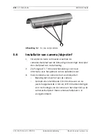
Отзывы: