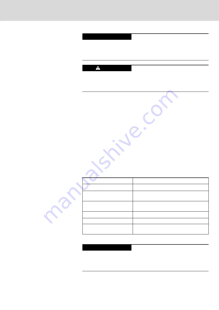
Destruction of screw terminals, insufficient
contact and loss of UL certificiation if no copper
wire is used and/or wrong tightening torque.
NOTICE
For terminal connectors use copper wire only. Tighten the screws of the screw
terminals with a torque of 2,20 lb in (0,22 Nm).
Risk of injury caused by voltage loss and non-
functioning stop button!
DANGER
For safety reasons, the voltage supply for the connection module (X1.1 pin1,
X1.2 pin1) is to be monitored. If the voltage fails, the STOP button at the device
is inoperative.
The connection module IndraControl VAC (the VAC 30.2 includes an automatic
stop button jumpering) is supplied with voltage via X1.1 pin1 or X1.2 pin1. The
connected hand-held terminal is supplied with voltage via X1.1 Pin3 or X1.2
Pin3. To make the hand-held terminal engageable or disengageable when it is
plugged-on, the wire jumper between X1.2 pin1 and X1.2 pin3 is to be removed
and the switching voltage for the hand-held terminal is to be applied to X1.1
pin3 or X1.2 pin3.
In contrast to the IndraControl VAC 30.2, the previous variant IndraControl VAC
30.1 was neither equipped with a separated voltage supply nor with a signal
contact. The pins 4 and 3 of the terminal blocks X1.1 and X1.2 are not available
on the IndraControl VAC 30.1 All existing pins of the VAC 30.1 connection
module are compatible with the IndraControl VAC 30.2 pins.
7.4.3
X1: DC 24 V Voltage Supply
All internally required voltages are generated with electrical isolation via a DC/
DC converter. The connection is designed as male connector strip S, 3.50 mm
pin spacing, so that cables up to a maximum line cross-section of 1.5 mm
2
can
be connected.
Parameter
Value
Rated voltage U
N
DC 24 V ; (+19 V to +30 V)
Residual ripple at U
N
fig. 7-17 "Limit values of the DC 24 V voltage"
.
Emitted interference and surge
immunity
U
max
= 35 V (for t < 100 ms)
Current consumption for U
N
0.7 A max.
Prescribed external protection
Fusible cut-out, 2 A time-lag
Reverse voltage protection
Occurs via decoupling diode; the line-side fuse is
activated when polarity reversal occurs.
Fig.7-15:
DC 24 V connection, technical data
Possible damages due to missing protection of
the 24 V lead.
NOTICE
The external voltage supply must have a rated voltage of 24 V and must not
exceed an output voltage of 30 V. The 24 V line to the connection module is to
be protected by a 2 A time-lag fusible cut-out.
DOK-SUPPL*-VCH*08.1***-PR02-EN-P
Rexroth IndraControl VCH 08.1 Hand-held Terminal
Bosch Rexroth AG
79/117
Pin Assignments of the IndraControl VCH 08.1
Содержание Rexroth VCH 08.1
Страница 1: ...Electric Drives and Controls Pneumatics Service Linear Motion and Assembly Technologies Hydraulics ...
Страница 12: ...Bosch Rexroth AG DOK SUPPL VCH 08 1 PR02 EN P Rexroth IndraControl VCH 08 1 Hand held Terminal 10 117 ...
Страница 28: ...Bosch Rexroth AG DOK SUPPL VCH 08 1 PR02 EN P Rexroth IndraControl VCH 08 1 Hand held Terminal 26 117 ...
Страница 60: ...Bosch Rexroth AG DOK SUPPL VCH 08 1 PR02 EN P Rexroth IndraControl VCH 08 1 Hand held Terminal 58 117 ...
Страница 92: ...Bosch Rexroth AG DOK SUPPL VCH 08 1 PR02 EN P Rexroth IndraControl VCH 08 1 Hand held Terminal 90 117 ...
Страница 114: ...Bosch Rexroth AG DOK SUPPL VCH 08 1 PR02 EN P Rexroth IndraControl VCH 08 1 Hand held Terminal 112 117 ...
Страница 118: ...Bosch Rexroth AG DOK SUPPL VCH 08 1 PR02 EN P Rexroth IndraControl VCH 08 1 Hand held Terminal 116 117 ...
Страница 119: ...Notes DOK SUPPL VCH 08 1 PR02 EN P Rexroth IndraControl VCH 08 1 Hand held Terminal Bosch Rexroth AG 117 117 ...


