9.4.4
Recording the jump response of the velocity loop
After the Kp and Tn values have been set, the jump response of the control‐
ler is recorded to check and/or further optimize the settings.
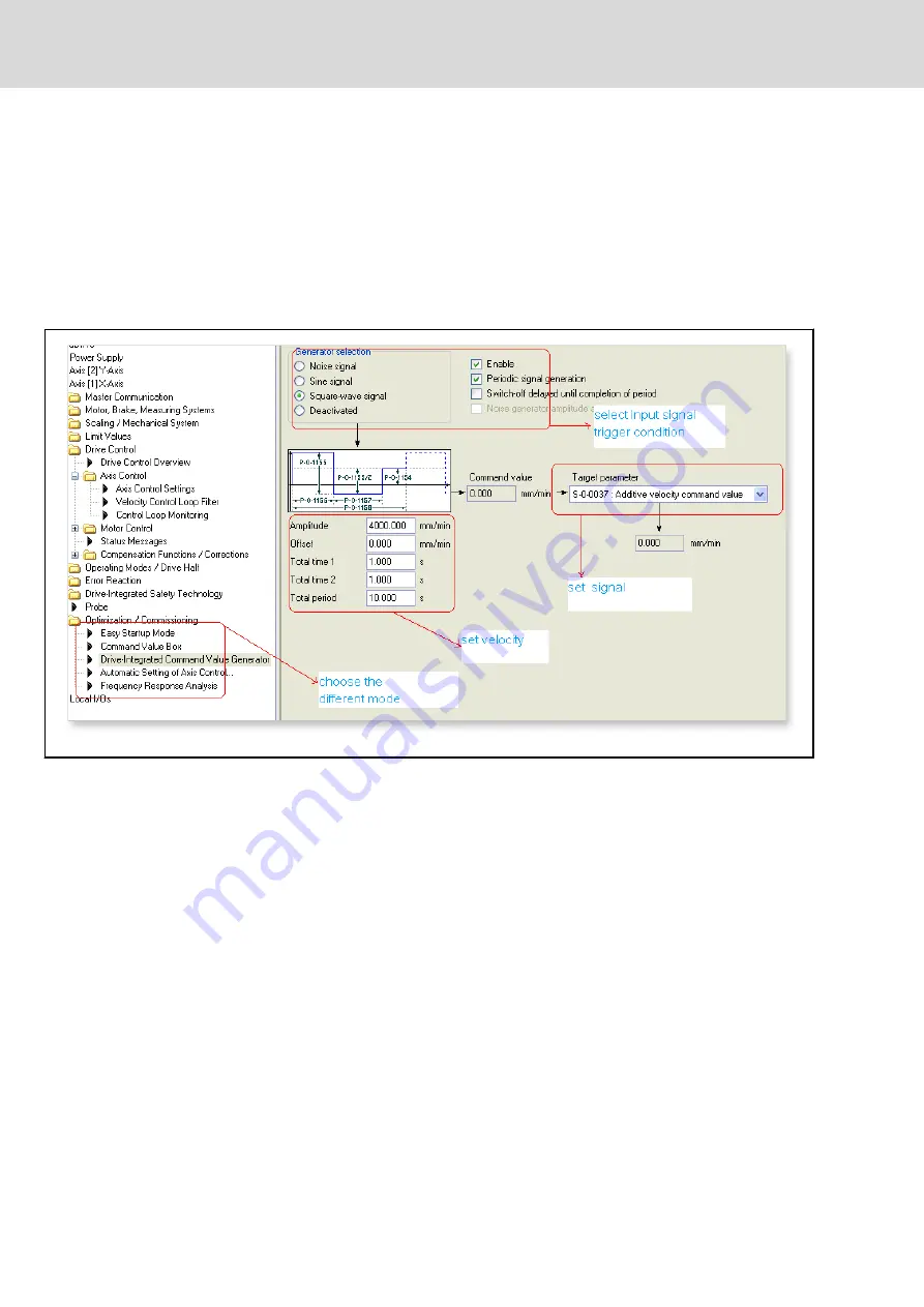
First select the "Square-wave signal" in the "Drive Integrated Command Val‐
ue Generator" dialog. Define the value of the amplitude according to Kp. In
general, we recommend that a value between 1000 mm/min and 2000
mm/min be selected for axes and a value between 10 rpm and 20 rpm for
spindles. Select S-0-0037 from the "Target parameter" box. Then select "pe‐
riodic signal generation".
Fig. 9-15:
"Drive-integrated command value generator"
Open the "Oscilloscope" on the Engineering Desktop under "Diagnostics".
Then configure the "Recording time" and the "Memory depth" according to
the values in the "Drive-integrated command value generator". Select "Con‐
figure" and set "Trigger", "Trigger signal", "Threshold value", and "Edge" ac‐
cordingly. Select the signals to be measured by clicking on "Signals". A maxi‐
mum of 4 signals can be measured at the same time. The signals required in
the example are S-0-0040 (current velocity), S-0-0084 (current torque) and
S-0-0189 (current lag error).
Bosch Rexroth AG
DOK-MTXMIC-EASY*******-CO06-EN-P
114/177
IndraMotion MTX micro Easy Setup for Standard Turning and Milling Machines
Commissioning the drives


