background image

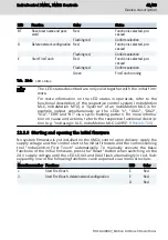
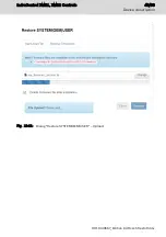
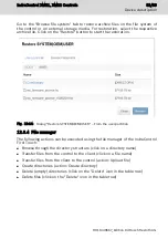
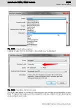
Go to the "Browse file system" tab to restore archive files on the file system of

the control or on external storage media. For restoration, select the respective

archive file. Click on the "Restore" button to start the restoration.

Fig.  12-14:   Dialog "Restore SYSTEM|OEM|USER" – From the user partition

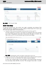
12.3.4  File manager

The following actions can be executed using the file manager of the IndraControl

First Touch:

Browse through the directory structure (click on a directory name)

Transfer files from the control to the client (click on a file name)

Transfer files from the client to the control (action: Upload file)

Create directories (action: Create directory)

Delete (empty) directories (click on the "Delete" icon in the table row)

Delete files (click on the "Delete" icon in the table row)

IndraControl XM21, XM22 Controls 

51/69

Device description

R911340667_Edition 04 Bosch Rexroth AG

Содержание Rexroth IndraControl XM21

Страница 1: ...IndraControl XM21 XM22 Controls Operating Instructions R911340667 Edition 04 ...

Страница 2: ...t of applications for industrial property rights Liability The specified data is intended for product description purposes only and shall not be deemed to be a guaranteed characteristic unless expressly stipulated in the contract All rights are reserved with respect to the content of this documen tation and the availability of the product Editorial Department Development Automation Systems Control...

Страница 3: ... symbol 4 3 3 Symbols used 5 3 4 Explaining the signal alert symbol on the device 5 4 Intended Use 5 5 Spare parts accessories and wear parts 6 5 1 Power connectors 24 V 6 5 2 Bus base module for IndraControl XM21 XM22 6 5 3 Bus base module for IndraControl S20 I O 6 5 4 SD card 7 5 5 End clamp 7 5 6 Wear parts 7 6 Ambient conditions 7 7 Technical data 9 7 1 Voltage supply and current consumption ...

Страница 4: ... 25 10 7 1 External power supply unit 25 10 7 2 Voltage supply for the control 26 10 7 3 24 V voltage supply 27 10 7 4 Grounding 29 10 7 5 Shielding 30 11 Commissioning 30 11 1 Commissioning steps 30 11 2 Establishing a connection to the engineering PC via the USB device interface XF31 31 12 Device description 34 12 1 LEDs and operating elements 35 12 1 1 LEDs in the XD1 plug 35 12 1 2 LED block o...

Страница 5: ...me response 55 12 8 1 Programming example Exception handling in case of a PLC task watchdog 55 12 8 2 Programming example Cyclic monitoring of the CPU load 58 13 Error causes and troubleshooting 59 14 Maintenance 60 14 1 Regular maintenance tasks 60 15 Ordering information 60 15 1 Type code 61 15 2 Accessories and spare parts 62 16 Disposal 62 16 1 General Information 62 16 2 Return 62 16 3 Packag...

Страница 6: ...IV IndraControl XM21 XM22 Controls Bosch Rexroth AG R911340667_Edition 04 ...

Страница 7: ...embly installation Engineering Commissioning Operation Decommissioning Product phases Target groups Activities Design engineer Programmer Technologist Process specialist Select Prepare Design Construct Mechanic electrician Unpack Mount Install Programmer Commissioning engineer Parameterize Program Configure Simulate Technologist Process specialist Optimize Test Machine operator Maintenance technic...

Страница 8: ...bus RT Ethernet Sercos CAN R911345570 Operating Instructions Tab 1 2 Related documents The XM2x controls are provided as function package with the systems IndraMotion MLC and IndraMotion MTX The ordering data type code part number differ according to the selected function package system functions The hardware characteristics described in this document apply to all available function packages For m...

Страница 9: ...ng 7 Plant number 8 QR code 9 Serial number 10 Underwriters Laboratories Inc mark 11 Nominal current 12 Nominal voltage 13 Company address 14 MAC address MAC address as barcode 15 Functional index 16 Manufacturing country Fig 2 1 Exemplary type plate 2 2 Additional plate 7260007123456BC I V C B T V R911173147 AA0 FI 001 1 Hardware state of revision Fig 2 2 Additional plate 2 3 Scope of delivery In...

Страница 10: ...ntain specific signal words danger warning caution notice and if necessary a safety alert symbol according to ANSI Z535 6 2006 The signal word draws attention to the safety instruction and indicates the risk potential The safety alert symbol triangular safety reflector with exclamation marks preceding the signal words Danger Warning Caution indicates hazards for persons DANGER In case of non compl...

Страница 11: ...s the steps required to avoid this hazard 4 Intended Use Danger of device damage if not the expressly stated accessories mounting parts compo nents cables lines software and firmware are used NOTICE The IndraControl XM21 XM22 control may only be used with the accessories and mounting parts listed in this documentation Components that are not ex pressly mentioned must neither be attached nor connec...

Страница 12: ...ription XA CN01 R911173741 24 V plug Tab 5 1 Power connectors 24 V 5 2 Bus base module for IndraControl XM21 XM22 Ordering code Part number Description XA BS01 R911342346 Bus base module for IndraControl S20 connection right XA BS02 R911342347 Bus base module for IndraControl S20 connection right and extension modules left Tab 5 2 Bus base modules IndraControl XM21 XM22 5 3 Bus base module for Ind...

Страница 13: ... transport 30 C to 85 C Operating altitude Up to 4 700 m above sea level acc to DIN 60204 Permitted air humidity 5 to 95 acc to DIN EN 61131 2 no conden sation Degree of protection IP20 acc to DIN EN 60 529 Protection class III DIN EN 61010 2 201 Overvoltage category 2 Contamination level 2 no condensation allowed Mechanical tests Vibration resistance acc to DIN EN 60068 2 6 Oscillations sinusoida...

Страница 14: ...at least comply with the degree of protection IP 54 according to DIN EN 60529 The device shall be provided in a suitable fire enclosure in the end use appli cation Defective product due to gases jeopardizing functions NOTICE Due to the risk of corrosion avoid sulphurous gases e g sulphur dioxide SO2 and hydrogen suphide H2S The product is not resistant against these gases Failure of the product du...

Страница 15: ...ngth 3 m for the functionality refer to the system description of the respective system 1 USB device maximum cable length 3 m for the functionality refer to the system description of the respective system SD card Slot for SD card Weight 0 38 kg incl supply connectors Dimensions Refer to chapter 10 2 Housing dimensions on page 19 Tab 7 1 Technical data 7 1 Voltage supply and current consumption The...

Страница 16: ...solation 24 V supply ULS to the functional earth No separation between 0 V of the ULS and FE housing Electrical isolation and isolation of the voltage ranges 24 V supply for XF1 XF2 and XF5 XF1 to XF2 and XF5 XF2 to XF5 1 200 V DC 1 min 1 200 V DC 1 min 1 200 V DC 1 min Tab 7 2 Operating voltage and current consumption Electronic damage due to polarity reversal or due to a nominal current that is ...

Страница 17: ...N EN 61131 2 Speicherprogrammierbare Steuerungen Teil 2 Betriebsmittelanforderungen und Prüfungen Programmable controllers Part 2 Equipment requirements and tests Automates programmables Partie 2 Spécifications et essais des équipements 2008 DIN EN 60529 Schutzarten durch Gehäuse IP Code Degrees of protection provided by enclosures IP Code Degrés de protection procurés par les enveloppes Code IP 2...

Страница 18: ... 201 UL Standard for Safety Requirements for Electrical Equipment for Measurement Control and Laboratory Use Part 2 201 Particular Requirements for Control Equipment 2014 Tab 8 1 Angewandte Normen Standards used Normes appliquées 8 2 CE marking 8 2 1 Declaration of conformity The electronic products described in the present operating instructions comply with the requirements and the target of the ...

Страница 19: ...y due to modifications at the device CE marking applies only to the device upon delivery After modifying the device verify the CE conformity 8 3 UL CSA certified The devices are certified acc to UL 61010 2 201 Industrial Control Equipment and CSA22 2 No 61010 2 201 CSA However there can be combinations or extension stages with a limited or miss ing certification Thus verify the registration accord...

Страница 20: ...Lloyd s Register DCTC_30826 004 BV Bureau Veritas DCTC_30826 005 BSH Bundesamt für Seeschifffahrt und Hydrographie DCTC 30826 006 For more information refer to www boschrexroth com dcc Vornavi gation VorNavi cfm PageID p650746 9 Interfaces 9 1 Connection position 1 2 8 6 7 5 3 9 4 Fig 9 1 Interfaces Attaching and detaching connections under voltage can damage the control NOTICE Switch off the supp...

Страница 21: ...ol interfaces 9 2 Extension bus Up to three extension modules can be freely connected at the left of the control The extension modules have to be attached without any gaps via the extension bus base modules on the left side of the IndraControl XM21 XM22 and supplied with the same 24 V supply voltage Switch on and off the 24 V supply voltage of the extension modules synchronously with the IndraCont...

Страница 22: ... can be damaged or destroyed by electrostatic discharge Comply with the required safety measures against elec trostatic discharge ESD acc to EN 61340 5 1 when operating the control Mounting location The XM2x control has the degree of protection IP20 and is thus intended for the use in a closed control cabinet or control box terminal box of the degree of protection IP54 or higher Mounting rail Moun...

Страница 23: ...ules connected to them on the mounting rail and they are used as lat eral end elements Always fasten the left end clamp of the station before mounting the control This ensures the following It impedes the shifting of the control The installation place for the end clamps is guaranteed If the control has to be replaced there is sufficient space to separate the control from the S20 bus base modules T...

Страница 24: ... the supply air has to be measured under each line and its limit value has to be observed For information on ambient tem peratures refer to chapter 6 Ambient conditions on page 7 Additionally provide sufficient distance for mounting demounting plugs and cables For more information on mounting demounting and connecting lines refer to the application description IndraControl S20 System and Installat...

Страница 25: ...Mounting the control Damages at the contacts by tilting the modules NOTICE Attach the modules vertically on the mounting rail and remove them vertically from the mounting rail IndraControl XM21 XM22 Controls 19 69 Mounting demounting and electric installation R911340667_Edition 04 Bosch Rexroth AG ...

Страница 26: ...g NOTICE Fasten the top hat rail adequately Connect the top hat rail to a functional ground Mount the control on the top hat rail as the top hat rail is among other things used for heat dissipation and grounding Install the control in a control cabinet or an appropriate housing Mounting the control bus base module 1 Press the control bus base module on the top hat rail until all latchings are safe...

Страница 27: ... the control is not attached to the control bus base module Mounting S20 bus base modules 1 Press the S20 bus base modules for the S20 modules on the top hat rail on the right next to the control bus base module until all latchings are safely closed see A in the following figure 2 Move the first S20 bus base module see B to the left and connect the S20 bus base module with the bus base module of t...

Страница 28: ... The extension bus base modules can only be mounted if the control is not attached to the control bus base module Mounting extension bus base modules 1 Press the extension bus base modules for the extension modules on the top hat rail on the left next to the control bus base module until all latch ings are safely closed see A in the following figure 22 69 Mounting demounting and electric installat...

Страница 29: ...s on the premounted extension bus base mod ules 10 6 Demounting the control and the control bus base module To demount use a common tool such a slotted screwdriver with a 2 5 mm blade 10 6 1 Demounting steps Component destruction due to demounting un der voltage NOTICE Before mounting or demounting components disconnect the control including its components from voltage Removing the control from th...

Страница 30: ...ction of the first S20 bus base module by moving the bus base module of the control to the left by approximately 5 mm see A in the following figure 2 Separate the bus base module of the control from the connection of the first extension bus base module by moving the bus base module of the con trol to the right by approximately 5 mm 3 Use a suitable tool e g slotted screwdriver to enter into the la...

Страница 31: ...ial damage must be prevented Protection upon direct and indirect contact must be ensured by the specified measures connection to protective conductor insulation etc 10 7 1 External power supply unit Danger of lethal injury due to hazardous electric voltage DANGER Connect power supply units generating protective extra low voltage 24 V on ly to supply voltages designed for these power supply units N...

Страница 32: ...y of the S20 I O modules may not be branched off from the XD1 plug of the XMx control but with an own connecting cable to the external power supply unit instead The 24 V voltage supply has to be grounded For more detailed infor mation refer to the documentation of the power supply unit 10 7 2 Voltage supply for the control The control is supplied via the XD1 plug on the lower left Connect the powe...

Страница 33: ... and the contact b1 is bridged with b2 The control is set up to connect to a UPS in future variants Thus 2A is labeled with UPS However a UPS can only be used without bridges when a respective variant and a specific power connector are used 10 7 3 24 V voltage supply The voltage of 24 V can be supplied with or without electrical isolation Setup without electrical isolation An easy connection metho...

Страница 34: ...e category I 24 V 0 V Fig 10 15 Setup without electrical isolation Control does not start in case of reverse input voltage The feeding of 24 V at the XD1 connector is protected against polari ty reversal A polarity reversal of ULS and GND feeding does not dam age the device However the control does not start and the UL LED is not on Reference conductor connected to the protective conductor and set...

Страница 35: ... the voltage supply Observe the maximum currents when dimensioning the voltage supply The ope rating voltage allowed has to be applied directly to the device The voltage must also not be exceeded if there are variations in line voltage e g caused by different loads of the mains there are varying load states such as short circuit normal load lamp load or no load Connecting the reference conductor t...

Страница 36: ...parate grounding connection Potential equalization Potential equalization acc to DIN VDE 0100 part 540 has to be provided be tween the system parts and the voltage supply 10 7 5 Shielding Control failure due to insufficient shielding NOTICE Provide sufficient shielding The shielding reduces any effects of interferences on the system Observe the following when shielding Fasten the shielding as exte...

Страница 37: ... has to be completed Subsequently continue the commissioning 11 2 Establishing a connection to the engineering PC via the USB device interface XF31 Instead of using the Ethernet interface XF5 to commission the control or to use the commissioning tool IndraControl First Touch use the connection XF31 Connect the USB interface of your computer to the USB device connection XF31 via a common USB data o...

Страница 38: ...he list under Other de vices 3 Select Update driver software in the context menu of RNDIS Ethernet gadget 4 In the dialog select the entry Browse my computer for driver software 5 In the dialog select the entry Let me pick from a list of device drivers in my computer 32 69 Commissioning IndraControl XM21 XM22 Controls Bosch Rexroth AG R911340667_Edition 04 ...

Страница 39: ... Network adapters 7 Select the entry Microsoft corporation under Manufacturer Then se lect Remote NDIS compatible device under Network adapter IndraControl XM21 XM22 Controls 33 69 Commissioning R911340667_Edition 04 Bosch Rexroth AG ...

Страница 40: ...following message is displayed 12 Device description The XM2x controls are compact controls in the medium performance range with integrated interfaces of Ethernet Sercos and S20 local bus 34 69 Device description IndraControl XM21 XM22 Controls Bosch Rexroth AG R911340667_Edition 04 ...

Страница 41: ... for the error diagnostics there are multiple PEDs an operation mode switch and a Reset button on the front side of the IndraControl XM21 XM22 control 1 2 3 4 Reset button behind sliding plate LED display block of 10 Operation mode switch SF1 LEDs on power connector XD1 Fig 12 1 LED and operating element positions 12 1 1 LEDs in the XD1 plug ON UL T Fig 12 2 LEDs on the XD1 plug The following func...

Страница 42: ...tage The messages Prewarning and Shutdown are displayed at a high operating temperature together with the diagnostic display of the en gineering interface A temperature display is shown additionally The sensor for all these messages is located at a selected position in the power supply area The temperature display is only for visual represen tation purposes It displays neither the ambient temperat...

Страница 43: ...range green Error status warning error BT Red orange green Boot status D Red orange green Onboard S20 Diagnostics S20 bus E Red orange green Onboard S20 Error or warning of S20 devices Tab 12 2 LED block of 10 The displayed device states are firmware dependent and described in the functional description of the respective control system Rexroth IndraLogic XLC IndraMotion MLC 14 VRS Functional De sc...

Страница 44: ...three positions Switch position Function Property Up Run Engaged Center Stop Engaged Down Clear Sampling Refer to the functional description of the respective control system Rexroth IndraLogic XLC IndraMotion MLC 14 VRS Functional Description R911341700 12 1 4 Reset button The Reset button is positioned on the higher located area of the control hous ing 38 69 Device description IndraControl XM21 X...

Страница 45: ...tingly Triggering the initial firmware see chapter 12 2 XM2x initial firm ware on page 39 The Reset button can only be actuated with a sharp tool e g pen cil 12 2 XM2x initial firmware The control variant XM2x00 01 is delivered with initial firmware The initial firmware provides commissioning and maintenance functions Basic functions can me activated manually without any additional tools see chapt...

Страница 46: ...e Bosch Rexroth AG Open Source Office Zum Eisengießer 1 97816 Lohr am Main Deutschland We may charge you a fee up to max 20 to cover the cost of physical media and processing You may send your request i within three 3 years from the date you received the product that included the binary that is the subject of your request or ii in the case of code licensed under the GPL v3 for as long as Bosch Rex...

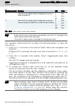
Страница 47: ...yclic flashing pattern For more informa tion on cause and actions refer to the respective functional descrip tion e g IndraLogic XLC IndraMotion MLC 14VRS R911341700 12 2 3 Starting and opening the initial firmware No system firmware is yet installed on the XM2x control upon delivery Apply the supply voltage and the control starts the initial firmware and the commissioning tool IndraControl First ...

Страница 48: ... changes from red to green Triggering the function is displayed by a brief switch off and switch on of the respective LEDs 3 To confirm the Factory reset menu item no 4 the operation mode switch SF1 has to be set to the Run position The left column is flashing until the additional confirmation of the opera tion mode switch is on the Run position The process of restoring the state upon delivery is ...

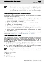
Страница 49: ...n the ERR LED is off and the E LED is green 6 Use the Reset button to execute a reboot required to start the control with system firmware The installation can be facilitated together with the Backup system firmware function see chapter 12 3 3 Firmware management on page 45 12 3 IndraControl First Touch The IndraControl First Touch commissioning application interactively commis sions and maintains ...

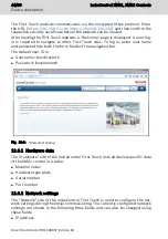
Страница 50: ...ID is User name boschrexroth Password boschrexroth Fig 12 6 Welcome dialog 12 3 1 Hardware data The Hardware site of the IndraControl First Touch lists all device specific data of the XM2x control in a table Material index Hardware type plate Serial number Part number 12 3 2 Network settings The Network site of the IndraControl First Touch is used to configure the net work settings during the init...

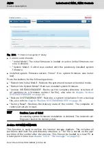
Страница 51: ...e Reboot control button is additionally displayed It is used to restart the control and thus applies the network setting Fig 12 7 Network configuration dialog The network settings are only applied after a control restart 12 3 3 Firmware management The Firmware management site of the IndraControl First Touch provides the following information IndraControl XM21 XM22 Controls 45 69 Device description...

Страница 52: ...ive SYSTEM OEM USER on page 46 Restore SYSTEM OEM USER Restores a system installation from a backup file also refer to chapter Restore SYSTEM OEM USER on page 48 Factory Reset Restores the delivery state of the control The complete di rectory structure is reset Caution Loss of data An existing system firmware installation is deleted The network set tings are reset to its delivery state Archive SYS...

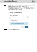
Страница 53: ...tension fw The backup can only be started if the selected file name corre sponds to the archive rules During as well as after the backup a corresponding message is displayed Fig 12 9 Dialog Archive SYSTEM OEM USER IndraControl XM21 XM22 Controls 47 69 Device description R911340667_Edition 04 Bosch Rexroth AG ...

Страница 54: ...em archive file can either be selected from the local file sys tem or from the file system of the control If the system archive file is selected from the local file system the archive is installed in two steps 1 Transferring the system archive file to the control 2 Installing the archive 48 69 Device description IndraControl XM21 XM22 Controls Bosch Rexroth AG R911340667_Edition 04 ...

Страница 55: ...Fig 12 11 Dialog Restore SYSTEM OEM USER Upload IndraControl XM21 XM22 Controls 49 69 Device description R911340667_Edition 04 Bosch Rexroth AG ...

Страница 56: ...Dialog Restore SYSTEM OEM USER Installation running Fig 12 13 Dialog Restore SYSTEM OEM USER Successfully completed 50 69 Device description IndraControl XM21 XM22 Controls Bosch Rexroth AG R911340667_Edition 04 ...

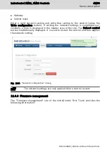
Страница 57: ...ns can be executed using the file manager of the IndraControl First Touch Browse through the directory structure click on a directory name Transfer files from the control to the client click on a file name Transfer files from the client to the control action Upload file Create directories action Create directory Delete empty directories click on the Delete icon in the table row Delete files click ...

Страница 58: ...nd file size in the Core dump menu item Click on the file name to transfer the files to the user PC via the browser specific download dialog Fig 12 16 Displaying the active core dump in IndraControl First Touch 2 Support of the user if the core dump could not be saved in the file system of the control e g not sufficient free memory space available Un this case storage space can be released in the ...

Страница 59: ...s shown After closing the dialog the core dump is displayed with its respective da ta 12 4 Booting The control starts booting after switching on the 24 V voltage supply Booting can be monitored and checked using different LEDs The following boot sequence is defined 1 The LED UL at the 24 V plug is green if 24 V is connected 2 The LED ON at the 24 V plug is green if the programmable logic is proper...

Страница 60: ...he Reset button SF2 If the display LED ON at the control XM2x is on the error is eliminated If the display LED ON at the control XM2x is not on initiate the Fallback mode for the extension modules whose display LED ON is not on 3 Keep the Fallback pushbutton of the respective module pressed using a plastic pen until the display LED ON is on at the extension module This loads a backup data set Rele...

Страница 61: ...the control It is recommended to set the time via SNTP 12 8 Real time response Full capability is ensured within the specified operating temperature range be tween 25 C and 60 C If the device is used beyond the specification ope rating temperature exceeds 60 C ensure sufficient convection in the control cabinet or monitor the CPU load applicatively to ensure real time response 12 8 1 Programming e...

Страница 62: ...ts and outputs are reset It is additionally possible to execute a customized code once and as soon as the error is detected Define a respective event handler in the task configuration Fig 12 19 Adding event handlers Select Exception as event 56 69 Device description IndraControl XM21 XM22 Controls Bosch Rexroth AG R911340667_Edition 04 ...

Страница 63: ... Specifying the function name The POU watchdog is created in the project tree and the event handler is ena bled Program the analysis of the exception code as shown in the following fig ure and your user code IndraControl XM21 XM22 Controls 57 69 Device description R911340667_Edition 04 Bosch Rexroth AG ...

Страница 64: ...ng mode before the watchdog shuts it down completely Measure the CPU load in normal mode and specify a suitable threshold value for a special handling in the PLC program The code has to be called cyclically within the PLC Example Cyclic analysis of the CPU load in the PLC user program 1 Fig 12 23 Definition of a global variable e g gboOverload to display an invalid ex ceedance of the CPU load 2 58...

Страница 65: ...with reverse polarity ON LED is off Error when loading the programmable logic Initiate fallback mode see chapter 12 5 Fallback and recovery on page 54 T LED is red Temperature error Control was switched off due to overheating Ensure a lower ambient temperature Check the control installation Avoid heat accumulation impeding the natural convection Tab 13 1 LEDs in the voltage power connector Further...

Страница 66: ...oth Service 14 Maintenance Maintenance work in the device is only permis sible by skilled staff NOTICE If hardware or software components have to be exchanged please contact the Bosch Rexroth Service or ensure that only skilled staff changes the respective components 14 1 Regular maintenance tasks Include the following tasks into the maintenance schedule Check all plug and terminal connections of ...

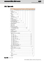
Страница 67: ...ard NN System configuration IndraMotion MLC 1 Basic system Function package PLC 00 PLC MOT 01 PLC MOT TEC 02 PLC MOT ROCO 03 PLC MOT TEC ROCO 04 PLC MOT HYD 05 PLC MOT TEC HYD 06 PLC MOT ROCO HYD 07 PLC MOT TEC ROCO HYD 08 PLC MOTB 11 PLC MOTB TEC 12 PLC MOTB ROCOB 13 PLC MOTB TEC ROCOB 14 PLC MOTB HYD 15 PLC MOTB TEC HYD 16 PLC MOTB ROCOB HYD 17 PLC MOTB TEC ROCOB HYD 18 Field bus prot f MultiEth...

Страница 68: ...aße 2 D 97816 Lohr am Main Germany 16 3 Packaging The packaging material consists of cardboard plastics wood or styrofoam Packaging material can be recycled anywhere For ecological reasons please do not return empty packages to Bosch Rexroth 17 Service and support Our worldwide service network provides an optimized and efficient support Our experts offer you advice and assistance should you have a...

Страница 69: ... on the internet Preparing information To be able to help you more quickly and efficiently please have the following in formation ready Detailed description of malfunction and circumstances Type plate specifications of the affected products in particular type codes and serial numbers Your contact data phone and fax number as well as your e mail address IndraControl XM21 XM22 Controls 63 69 Service...

Страница 70: ...64 69 IndraControl XM21 XM22 Controls Bosch Rexroth AG R911340667_Edition 04 ...

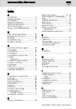
Страница 71: ...ances 18 Distances for cooling 18 Documentation Change record 1 Documents related 2 E Electric Installation 25 Electrical isolation 27 28 Electromagnetic compatibility 12 EMC 12 Emitted interference 8 End clamp 7 17 Error causes 59 Extension bus 15 Extension modules Mounting 22 External power supply unit 25 F Fallback 54 Feedback 2 File manager 51 Firmware management 45 Functional earth 30 G Groun...

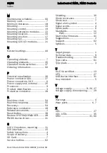
Страница 72: ...Reference conductor 28 Related documents 2 Reset button 38 Restore SYSTEM OEM USER 48 RNDIS device driver 31 S S20 I O modules mounting 21 S20 interface 15 Safety instructions 4 Scope of delivery 3 SD Card 7 Service hotline 62 Shielding 30 Shock resistance 7 Shock test 7 Signal alert symbol 4 Signal words 4 Spare parts 6 Standards 11 EMC 12 Start initial firmware 41 Suggestions 2 Support 62 Symbol...

Страница 73: ...IndraControl XM21 XM22 Controls 67 69 R911340667_Edition 04 Bosch Rexroth AG ...

Страница 74: ...68 69 IndraControl XM21 XM22 Controls Bosch Rexroth AG R911340667_Edition 04 ...

Страница 75: ...Notes IndraControl XM21 XM22 Controls 69 69 ...

Страница 76: ...Electric Drives and Controls P O Box 13 57 97803 Lohr Germany Bgm Dr Nebel Str 2 97816 Lohr Germany Phone 49 9352 18 0 Fax 49 9352 18 8400 www boschrexroth com electrics R911340667 R911340667 DOK CONTRL IC XM2 IT04 EN P ...

Отзывы: