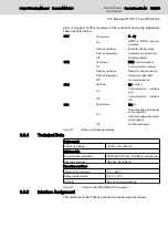
gram is stopped. Further meanings of the indicators during the initialization
phase are listed below.
RDY
LED yellow
Ready
On:
DPM01 or DPS01 ready for
operation
Flashes cyclically
Bootstrap loader active
Flashes irregularly
Hardware or system error
Off:
Hardware defect
RUN
LED green
RUN (communication)
On:
Communication running
Flashes cyclically
Ready for communication
Flashes irregularly
Inproper configuration
Off:
No communication
ERR
LED red
Error (error)
On:
Communication interface
error
Off:
Communication interface
OK
STA
LED yellow
Status
On:
Data exchange with slaves
active (master)
Data exchange with master
active (slave)
Off:
No data exchange
Fig.9-23:
Status and diagnosis displays
9.6.4
Technical Data
Power supply
Operating voltage:
+5VDC, ±5% / 650 mA
Interface data
Communication interface:
PROFIBUS DP, max. 12 MBaud, potential-free
Diagnosis interface:
RS 232C, 9600 Baud
Operating conditions
Operating temperature:
0°C - +55°C
Storage temperature:
-25°C - +70°C
Humidity:
max. 75% non-condensing
Fig.9-24:
Technical data PROFIBUS DP connection
9.6.5
Interface Assignment
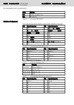
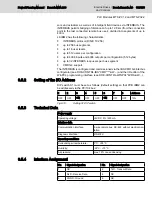
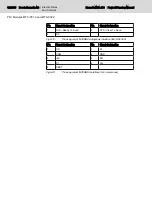
The interfaces of the Profibus connections are assigned as follows:
Project Planning Manual | Rexroth MTA 200
Electric Drives
and Controls
| Bosch Rexroth AG 123/135
PLC Modules MTS-P01.2 and MTS-P02.2
Содержание Rexroth BTV 20.4A
Страница 1: ...Electric Drives and Controls Pneumatics Service Linear Motion and Assembly Technologies Hydraulics ...
Страница 12: ...10 135 Bosch Rexroth AG Electric Drives and Controls Rexroth MTA 200 Project Planning Manual ...
Страница 66: ...64 135 Bosch Rexroth AG Electric Drives and Controls Rexroth MTA 200 Project Planning Manual ...
Страница 134: ...132 135 Bosch Rexroth AG Electric Drives and Controls Rexroth MTA 200 Project Planning Manual ...
Страница 137: ...Notes Project Planning Manual Rexroth MTA 200 Electric Drives and Controls Bosch Rexroth AG 135 135 ...

