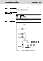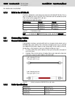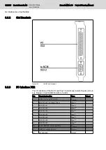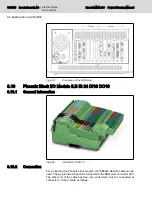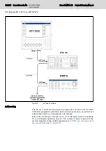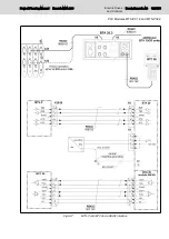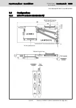
Fig.9-5:
BT bus overview
Addressing
The BT bus is addressed by assigning a logical user number in the I/O editor
of the PLC programming interface. Each input image memory, as well as each
output image memory, is assigned its own address.
Each of the two image memories has a size of 128 bytes, which are available
for the connected operating devices. The number of bytes assigned in the
memory depends on the operator panel (see
fig. 9-6 "Memory requirements of
the operating devices" on page 113
112/135 Bosch Rexroth AG | Electric Drives
and Controls
Rexroth MTA 200 | Project Planning Manual
PLC Modules MTS-P01.2 and MTS-P02.2
Содержание Rexroth BTV 20.4A
Страница 1: ...Electric Drives and Controls Pneumatics Service Linear Motion and Assembly Technologies Hydraulics ...
Страница 12: ...10 135 Bosch Rexroth AG Electric Drives and Controls Rexroth MTA 200 Project Planning Manual ...
Страница 66: ...64 135 Bosch Rexroth AG Electric Drives and Controls Rexroth MTA 200 Project Planning Manual ...
Страница 134: ...132 135 Bosch Rexroth AG Electric Drives and Controls Rexroth MTA 200 Project Planning Manual ...
Страница 137: ...Notes Project Planning Manual Rexroth MTA 200 Electric Drives and Controls Bosch Rexroth AG 135 135 ...


