


About this product 31/104
RE 92076-01-B/10.2017, A4... with HS5E pilot control valve/Series 3x,
Bosch Rexroth AG
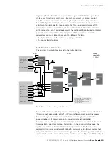
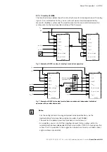
5.7.1 Circuitry of HS5E
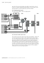
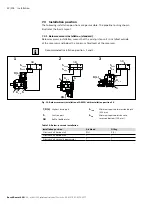
The two illustrations below show the circuitry for master/slave operation with analog
signals. As an alternative to this, you can also set up master/slave operation by
means of a fieldbus system and the machine control. For more information on this
system, refer to the functional description of the firmware.
P
U
XH4
XH4
1 U
B
2 L0
4 M0
5 α
set
α
actual
6
7 p
set
10 p
actual
high
11 p
actual
low
Master
α
set
(I)
p
set
(I)
U
B
0 V
1 U
B
2 L0
4 M0
5 α
set
7 p
set
10 p
actual
high
11 p
actual
low
Slave
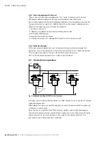
Fig. 6: Example of HS5E circuitry for (analog) master/slave operation
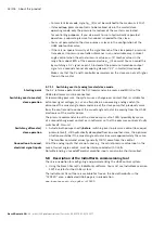
Fig. 7: Example of HS5E for (analog) master/slave operation and independent individual
operation with possible alternatives
notes:
– For the configuration of analog command value specification, see the
HydraulicDrive functional description (see data sheet 30338).
– The port for the pump's position transducer is not drawn in.
– As an option, you can install the coupling element (relay, analog switch) to
regulate both pumps independently from one another. With the slave pump, this
means that it is possible in the suggestion shown here to carry out both swivel
angle and pressure control.
P
U
P
U
XH4
XH4
U
B
0 V
α
set
(I)
p
set
(I)
1 U
B
2 L0
4 M0
5 α
set
7 p
set
10 p
actual
high
11 p
actual
low
α
act
6
Slave
p
set
(II)
0 V
α
set
(II)
Master/slave
operation ON
1 U
B
4 M0
11 p
actual
low
7 p
set
Master
2 L0
5 α
set
10 p
actual
high