background image

    Applications Manual                                                                                                                      Bosch Greenstar 


| 63


Bosch Thermotechnology Corp.

             Data subject to change

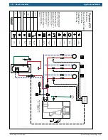
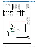
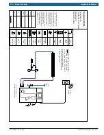
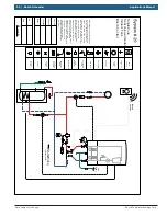
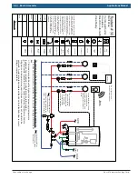
System #29

reset

eco

1

2

3

4

5

6

max

1

2

3

4

e

6

max

Boiler 

Heating 

Dial

1

2

3

Typical supply 
temperatures

approx.   95 °F (35 °C)

approx. 109 °F (43 °C)

approx. 122 °F (50 °C)

4

5

6

approx. 140 °F (60 °C)

approx. 153 °F (67 °C)

approx. 167 °F (75 °C)

max 

Approx. 194 °F (90°C)

Application

Frost protection

Radiant floor heating

Panel radiator system

Cast Iron radiator system

Baseboard & convector system

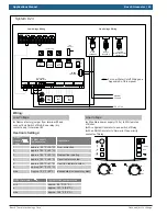
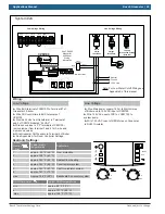
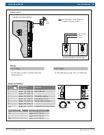
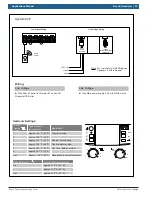
Heatronic Settings:

Low Voltage

Wiring:

Line Voltage

Heatronic Internal Wiring

L

N

G

External Boiler Junction box

120 Vac Supply

B

B

4

2

1

A

F

9

7

8

LWCO

Supply Sensor

DHW Sensor

Dry contacts

Bosch Controls

Outdoor 
Sensor

Ź

 Wire BUS terminal of the Bosch Control to 

Terminal BB of Greenstar boiler

Ź

 Wire Main power supply (120 v) to White molex

     of Boiler (external junction box) 

Ź

 Wire 120 VAC of Black Molex to Zone Circulator 

Ź

  Wire Supply Sensor to terminals in the Heatronic 

     control

DHW Thermistor

Ź

 Wire Greenstar Tank thermistor sensor to blue 

    molex adaptor in Greenstar boiler wire harness

DHW

Circulator

Ź

 Wire 120 VAC of Red Molex to DHW Circulator

L

N

red

storage

tank pump

L

N

black

ch pump 

for unmixed heating

L

N

white

mains

120v/60 hz

Note: For Low Water Cutoff Wiring see 
          Appendix D of this manual 

Supply Sensor

DHW thermostat 

min

e

max

Typical DHW temperatures

approx. 59 °F (15 °C)

approx. 131 °F (55 °C)

approx. 158 °F (70 °C)

Bosch

Control

Zone

Circulator

Содержание FS 100

Страница 1: ...y company In Massachusetts the boiler must be installed by a licensed plumber or gas fitter Application drawings in this manual are conceptual only and do not purport to address all design installation code or safety considerations The diagrams in this manual are for reference use by code officials designers and licensed installers It is expected that installers have adequate knowledge of national...

Страница 2: ...2 Bosch Greenstar Applications Manual Bosch Thermotechnology Corp Data subject to change ...

Страница 3: ... Zone Baseboard with Bosch CRC control 20 Multi Zone Systems using Circulators 22 System 9 Greenstar Combi Wall Boiler Multi zone system using circulators with standard zone relay FW200 optional 22 System 10 Greenstar Combi Wall Boiler Multi zone system using circulators and Bosch Comfort Zone Manager CZM100 24 System 11 Greenstar Combi Floor Boiler Multi zone system using circulators with standar...

Страница 4: ...standard zone relay FW200 optional and indirect tank 50 System 24 Greenstar Heat Only Floor Boiler Multi zone system using zone valves and Bosch Comfort Zone Manager CZM100 and indirect tank 52 Single Multi Zone Systems using Bosch Control 54 System 25 Greenstar Combi Wall Boiler Single zone baseboard with Bosch Control 54 System 26 Greenstar Combi Floor Boiler Single zone baseboard with Bosch Con...

Страница 5: ...lowing keywords are defined and can be used in this document DANGER indicates a hazardous situation which if not avoided will result in death or serious injury WARNING indicates a hazardous situation which if not avoided could result in death or serious injury CAUTION indicates a hazardous situation which if not avoided could result in minor to moderate injury NOTICE is used to address practices n...

Страница 6: ...te flow rates Purge Drain DISCLAIMER Application drawings in this manual are conceptual only and do not purport to address all design installation code or safety considerations The diagrams in this manual are for reference use by code officials designers and licensed installers It is expected that installers have adequate knowledge of national and local codes as well as accepted industry practices...

Страница 7: ...upply 120 v to White molex Ź install FW200 on front of boiler see manual Ź install outdoor air sensor Ź Follow FW200 Quick Set up guide in Greenstar Manual If using FW200 Optional Heatronic Settings Ź Remove factory jumper from terminal 2 4 inside Heatronic control and connect non power robbing thermostat dry contacts only Outdoor Sensor Ź install FW200 on front of boiler see manual Ź install outd...

Страница 8: ...ual are for reference use by code officials designers and licensed installers It is expected that installers have adequate knowledge of national and local codes as well as accepted industry practices and are trained on equipment procedures and applications involved Drawings are not to scale Refer to the boiler control and module installer manuals for additional detailed information Domestic Cold W...

Страница 9: ...Radiant floor heating Panel radiator system Cast Iron radiator system Baseboard convector system CRC100 or CRC200 Bosch Low Voltage Wiring Line Voltage Ź Wire Comfort Room Controller CRC100 or CRC200 to Terminals B B of Heatronic control Ź Wire Main power supply 120 v to White molex Ź See Appendix A for Room Controller Settings Heatronic Settings Heatronic Internal Wiring B B 4 2 1 A F 9 7 8 LWCO ...

Страница 10: ...installers have adequate knowledge of national and local codes as well as accepted industry practices and are trained on equipment procedures and applications involved Drawings are not to scale Refer to the boiler control and module installer manuals for additional detailed information Domestic Cold Water Domestic Hot Water Gas Supply PRV Relief piping Note Internal Low Loss Header in closed posit...

Страница 11: ... approx 140 F 60 C approx 153 F 67 C approx 167 F 75 C max Approx 194 F 90 C Application Frost protection Radiant floor heating Panel radiator system Cast Iron radiator system Baseboard convector system Neutral 120 V Line Ground Low Voltage Wiring Line Voltage Wiring Heatronic Settings Low Voltage Ź Remove factory jumper from terminal 2 and connect non power robbing thermostat dry contacts only to...

Страница 12: ... have adequate knowledge of national and local codes as well as accepted industry practices and are trained on equipment procedures and applications involved Drawings are not to scale Refer to the boiler control and module installer manuals for additional detailed information Domestic Cold Water Domestic Hot Water Gas Supply PRV Relief piping Bosch Bosch CRC100 or CRC200 Note Internal Low Loss Hea...

Страница 13: ...67 C approx 167 F 75 C max Approx 194 F 90 C Application Frost protection Radiant floor heating Panel radiator system Cast Iron radiator system Baseboard convector system Neutral 120 V Line Ground Low Voltage Wiring Line Voltage Wiring Bosch CRC100 or CRC200 Heatronic Settings Low Voltage Ź Wire Comfort Room Controller CRC100 or CRC200 to Terminal 1 on back of Greenstar FS Boiler Wiring Line Volta...

Страница 14: ... or safety considerations The diagrams in this manual are for reference use by code officials designers and licensed installers It is expected that installers have adequate knowledge of national and local codes as well as accepted industry practices and are trained on equipment procedures and applications involved Drawings are not to scale Refer to the boiler control and module installer manuals f...

Страница 15: ...n power supply 120 v to White molex Ź Remove factory jumper from terminal 2 4 inside Heatronic control and connect non power robbing thermostat dry contacts only Heatronic Settings Room Thermostat Outdoor Sensor Ź install FW200 on front of boiler see manual Ź install outdoor air sensor Ź Follow FW200 Quick Set up guide in Appendix C If using FW200 Optional Heatronic Internal Wiring B B 4 2 1 A F 9...

Страница 16: ...grams in this manual are for reference use by code officials designers and licensed installers It is expected that installers have adequate knowledge of national and local codes as well as accepted industry practices and are trained on equipment procedures and applications involved Drawings are not to scale Refer to the boiler control and module installer manuals for additional detailed informatio...

Страница 17: ...ystem Baseboard convector system CRC100 or CRC200 Bosch Ź See Appendix A for Room Controller Settings Low Voltage Wiring Line Voltage Ź Wire Comfort Room Controller CRC100 or CRC200 to Terminals B B of Heatronic control Ź Wire Main power supply 120 v to White molex Heatronic Settings Heatronic Internal Wiring B B 4 2 1 A F 9 7 8 LWCO Supply Sensor DHW Sensor Dry contacts Bosch Controls Outdoor Sen...

Страница 18: ...re for reference use by code officials designers and licensed installers It is expected that installers have adequate knowledge of national and local codes as well as accepted industry practices and are trained on equipment procedures and applications involved Drawings are not to scale Refer to the boiler control and module installer manuals for additional detailed information Gas Supply PRV Relie...

Страница 19: ... 194 F 90 C Application Frost protection Radiant floor heating Panel radiator system Cast Iron radiator system Baseboard convector system Neutral 120 V Line Ground Low Voltage Wiring Line Voltage Wiring Heatronic Settings Low Voltage Ź Remove factory jumper from terminal 2 and connect non power robbing thermostat dry contacts only to terminal 2 Wiring Line Voltage Ź Wire Main power supply 120 v to...

Страница 20: ...ference use by code officials designers and licensed installers It is expected that installers have adequate knowledge of national and local codes as well as accepted industry practices and are trained on equipment procedures and applications involved Drawings are not to scale Refer to the boiler control and module installer manuals for additional detailed information Gas Supply PRV Relief piping ...

Страница 21: ...otection Radiant floor heating Panel radiator system Cast Iron radiator system Baseboard convector system Neutral 120 V Line Ground Low Voltage Wiring Line Voltage Wiring Bosch CRC100 or CRC200 Heatronic Settings Low Voltage Wiring Line Voltage Ź Wire Main power supply 120 v to White molex Ź Wire Comfort Room Controller CRC100 or CRC200 to Terminal 1 on back of Greenstar FS Boiler Ź See Appendix A...

Страница 22: ...code officials designers and licensed installers It is expected that installers have adequate knowledge of national and local codes as well as accepted industry practices and are trained on equipment procedures and applications involved Drawings are not to scale Refer to the boiler control and module installer manuals for additional detailed information T T T T T T Note Larger heating systems may ...

Страница 23: ...Line Voltage Ź Wire Main power supply 120 v to White molex of Boiler external junction box Outdoor Sensor Ź install FW200 on front of boiler see manual Ź install outdoor air sensor Ź Follow FW200 Quick Set up guide in Appendix C If using FW200 Optional Heatronic Internal Wiring B B 4 2 1 A F 9 7 8 LWCO Supply Sensor DHW Sensor Dry contacts Bosch Controls Outdoor Sensor Supply Sensor end switch T T...

Страница 24: ...ers and licensed installers It is expected that installers have adequate knowledge of national and local codes as well as accepted industry practices and are trained on equipment procedures and applications involved Drawings are not to scale Refer to the boiler control and module installer manuals for additional detailed information T T T T T T Note Larger heating systems may require an additional...

Страница 25: ...Z2 PZ1 120 VAC L N L N L N L N 24 V BUS 1 2 1 2 1 2 1 2 BUS BUS BUS 120 VAC 1 4 5 6 0 3 2 1 2 3 4 See CZM100 Manual for additional Wiring information B B 4 2 1 A F 9 7 8 LWCO Supply Sensor DHW Sensor Dry contacts Bosch Controls Outdoor Sensor Supply Sensor Ź Wire BUS terminal of CZM100 to Terminal BB of Greenstar boiler Ź Wire Main power supply 120 v to White molex of Boiler external junction box ...

Страница 26: ...iagrams in this manual are for reference use by code officials designers and licensed installers It is expected that installers have adequate knowledge of national and local codes as well as accepted industry practices and are trained on equipment procedures and applications involved Drawings are not to scale Refer to the boiler control and module installer manuals for additional detailed informat...

Страница 27: ... max Approx 194 F 90 C Application Frost protection Radiant floor heating Panel radiator system Cast Iron radiator system Baseboard convector system Neutral 120 V Line Ground Low Voltage Wiring Line Voltage Wiring Heatronic Settings Low Voltage Ź Remove factory jumper from terminal 2 and connect End Switch of Mult Zone relay dry contacts only to terminal 2 Wiring Line Voltage Ź Wire Main power sup...

Страница 28: ...e use by code officials designers and licensed installers It is expected that installers have adequate knowledge of national and local codes as well as accepted industry practices and are trained on equipment procedures and applications involved Drawings are not to scale Refer to the boiler control and module installer manuals for additional detailed information Domestic Cold Water Domestic Hot Wa...

Страница 29: ...al 120 V Line Ground Low Voltage Wiring Line Voltage Wiring Heatronic Settings Low Voltage Ź Wire BUS terminal of CZM100 to Terminal 1 of Greenstar FS boiler Wiring Line Voltage Ź Wire Main power supply 120 v to White molex of Boiler and to 120 VAC input of CZM100 Bosch Bosch Bosch CRC100 or CRC200 Ź Wire CRC controllers to BUS terminals of CZM100 Ź Wire 120 VAC ouputs of PZ1 PZ2 and PZ3 to Zone C...

Страница 30: ...ations The diagrams in this manual are for reference use by code officials designers and licensed installers It is expected that installers have adequate knowledge of national and local codes as well as accepted industry practices and are trained on equipment procedures and applications involved Drawings are not to scale Refer to the boiler control and module installer manuals for additional detai...

Страница 31: ...If using FW200 Optional External Boiler Junction box 120 Vac Supply Heatronic Internal Wiring B B 4 2 1 A F 9 7 8 LWCO Supply Sensor DHW Sensor Dry contacts Bosch Controls Outdoor Sensor Supply Sensor Ź Wire 120 Vac power supply to zone relay end switch T T T T T T X1 X2 Zone 3 Zone 1 Zone 2 H N Zone 3 Zone 1 Zone 2 H N H N Priority Zone H N Priority Zone 120 Vac Power DHW Sensor Note Only use a p...

Страница 32: ...agrams in this manual are for reference use by code officials designers and licensed installers It is expected that installers have adequate knowledge of national and local codes as well as accepted industry practices and are trained on equipment procedures and applications involved Drawings are not to scale Refer to the boiler control and module installer manuals for additional detailed informati...

Страница 33: ... See CZM100 Manual for additional Wiring information B B 4 2 1 A F 9 7 8 LWCO Supply Sensor DHW Sensor Dry contacts Bosch Controls Outdoor Sensor Ź Wire BUS terminal of CZM100 to Terminal BB of Greenstar boiler Ź Wire Main power supply 120 v to White molex of Boiler external junction box and to 120 VAC input of CZM100 Ź Wire CRC controllers to BUS terminals of CZM100 See Appendix A for Room Contro...

Страница 34: ...purport to address all design installation code or safety considerations The diagrams in this manual are for reference use by code officials designers and licensed installers It is expected that installers have adequate knowledge of national and local codes as well as accepted industry practices and are trained on equipment procedures and applications involved Drawings are not to scale Refer to th...

Страница 35: ...r system Neutral 120 V Line Ground Low Voltage Wiring Line Voltage Wiring Heatronic Settings Low Voltage Ź Remove factory jumper from terminal 2 and connect End Switch of Mult Zone relay dry contacts only to terminal 2 Wiring Line Voltage Ź Wire Main power supply 120 v to White molex of Boiler end switch T T T T T T X1 X2 Zone 3 Zone 1 Zone 2 H N Zone 3 Zone 1 Zone 2 H N H N Priority Zone H N Prio...

Страница 36: ...n code or safety considerations The diagrams in this manual are for reference use by code officials designers and licensed installers It is expected that installers have adequate knowledge of national and local codes as well as accepted industry practices and are trained on equipment procedures and applications involved Drawings are not to scale Refer to the boiler control and module installer man...

Страница 37: ...Ź Wire BUS terminal of CZM100 to Terminal 1 of Greenstar FS boiler Wiring Line Voltage Ź Wire Main power supply 120 v to White molex of Boiler and to 120 VAC input of CZM100 CRC100 or CRC200 Ź Wire CRC controllers to BUS terminals of CZM100 Ź Wire 120 VAC ouputs of PZ1 PZ2 and PZ3 to Zone Circulators Ź Wire Greenstar Tank sensor to Terminal 5 of Greenstar FS boiler DHW Pump Ź Wire Red molex on bac...

Страница 38: ...fficials designers and licensed installers It is expected that installers have adequate knowledge of national and local codes as well as accepted industry practices and are trained on equipment procedures and applications involved Drawings are not to scale Refer to the boiler control and module installer manuals for additional detailed information T T T T T T Note Larger heating systems may requir...

Страница 39: ...y dry contacts only Wiring Line Voltage Ź Wire Main power supply 120 v to White molex of Boiler external junction box Outdoor Sensor If using FW200 Optional Heatronic Internal Wiring B B 4 2 1 A F 9 7 8 LWCO Supply Sensor Dry contacts Bosch Controls Outdoor Sensor Supply Sensor External Boiler Junction box 120 VAC Ź Wire 120 Vac power supply to zone relay Zone 1 1 2 3 4 Zone 3 1 2 3 4 Zone 4 1 2 3...

Страница 40: ...ficials designers and licensed installers It is expected that installers have adequate knowledge of national and local codes as well as accepted industry practices and are trained on equipment procedures and applications involved Drawings are not to scale Refer to the boiler control and module installer manuals for additional detailed information T T T T T T Note Larger heating systems may require...

Страница 41: ...rotection Radiant floor heating Panel radiator system Cast Iron radiator system Baseboard convector system Heatronic Settings Low Voltage Wiring Line Voltage Heatronic Internal Wiring B B 4 2 1 A F 9 7 8 LWCO Supply Sensor Dry contacts Bosch Controls Outdoor Sensor Ź Wire BUS terminal of CZM100 to Terminal BB of Greenstar boiler Heatronic control Ź Wire Main power supply 120 v to White molex of Bo...

Страница 42: ...ms in this manual are for reference use by code officials designers and licensed installers It is expected that installers have adequate knowledge of national and local codes as well as accepted industry practices and are trained on equipment procedures and applications involved Drawings are not to scale Refer to the boiler control and module installer manuals for additional detailed information D...

Страница 43: ...tronic Settings Low Voltage Ź Remove factory jumper from terminal 2 and connect End Switch of Multi Zone relay dry contacts only to terminal 2 Wiring Line Voltage Ź Wire Main power supply 120 v to White molex of Boiler Zone 1 1 2 3 4 Zone 3 1 2 3 4 Zone 4 1 2 3 4 Zone 2 1 2 3 4 T T Zone 1 T T Zone 2 T T Zone 3 T T Zone 4 End switch End switch Zone 4 relay N O Com N C off on Zone 4 priority 24 VAC ...

Страница 44: ...use by code officials designers and licensed installers It is expected that installers have adequate knowledge of national and local codes as well as accepted industry practices and are trained on equipment procedures and applications involved Drawings are not to scale Refer to the boiler control and module installer manuals for additional detailed information Domestic Cold Water Domestic Hot Wate...

Страница 45: ...M100 to Terminal 1 of Greenstar FS boiler Wiring Line Voltage Ź Wire Main power supply 120 v to White molex of Boiler and to 120 VAC input of CZM100 See CZM100 Manual for Detail wiring CRC100 or CRC200 CZM100 Ź Wire CRC controllers to BUS terminals of CZM100 Ź Wire 120 VAC ouput of PZ1 to system pump Bosch Bosch VZ3 VZ1 T0 24VAC VZ2 1 2 1 2 1 2 1 2 1 2 3 4 3 4 3 4 24 VAC Transformer 2 wire 3 wire ...

Страница 46: ...on code or safety considerations The diagrams in this manual are for reference use by code officials designers and licensed installers It is expected that installers have adequate knowledge of national and local codes as well as accepted industry practices and are trained on equipment procedures and applications involved Drawings are not to scale Refer to the boiler control and module installer ma...

Страница 47: ...ly 120 v to White molex of Boiler Zone 1 1 2 3 4 Zone 3 1 2 3 4 Zone 4 1 2 3 4 Zone 2 1 2 3 4 T T Zone 1 T T Zone 2 T T Zone 3 T T Zone 4 End switch End switch Zone 4 relay N O Com N C off on Zone 4 priority 24 VAC Transformer 2 wire Zone valve 3 wire Zone valve 4 wire Zone valve Tank Aquastat Thermostats Ź Wire System Circulator to end switch of Relay Ź Wire DHW Circulator to Normally Open priori...

Страница 48: ...rations The diagrams in this manual are for reference use by code officials designers and licensed installers It is expected that installers have adequate knowledge of national and local codes as well as accepted industry practices and are trained on equipment procedures and applications involved Drawings are not to scale Refer to the boiler control and module installer manuals for additional deta...

Страница 49: ...oltage Wiring Line Voltage Heatronic Internal Wiring B B 4 2 1 A F 9 7 8 LWCO Supply Sensor Dry contacts Bosch Controls Outdoor Sensor Ź Wire BUS terminal of CZM100 to Terminal BB of Greenstar boiler Heatronic control Ź Wire Main power supply 120 v to White molex of Boiler external junction box and to 120 VAC input of CZM100 Ź Wire CRC controllers to BUS terminals of CZM100 See Appendix A for Room...

Страница 50: ...design installation code or safety considerations The diagrams in this manual are for reference use by code officials designers and licensed installers It is expected that installers have adequate knowledge of national and local codes as well as accepted industry practices and are trained on equipment procedures and applications involved Drawings are not to scale Refer to the boiler control and mo...

Страница 51: ...from terminal 2 and connect End Switch of Multi Zone relay dry contacts only to terminal 2 Wiring Line Voltage Ź Wire Main power supply 120 v to White molex of Boiler Zone 1 1 2 3 4 Zone 3 1 2 3 4 Zone 4 1 2 3 4 Zone 2 1 2 3 4 T T Zone 1 T T Zone 2 T T Zone 3 T T Zone 4 End switch End switch Zone 4 relay N O Com N C off on Zone 4 priority 24 VAC Transformer 2 wire Zone valve 3 wire Zone valve 4 wi...

Страница 52: ...onsiderations The diagrams in this manual are for reference use by code officials designers and licensed installers It is expected that installers have adequate knowledge of national and local codes as well as accepted industry practices and are trained on equipment procedures and applications involved Drawings are not to scale Refer to the boiler control and module installer manuals for additiona...

Страница 53: ...20 v to White molex of Boiler and to 120 VAC input of CZM100 CRC100 or CRC200 CZM100 Ź Wire CRC controllers to BUS terminals of CZM100 Ź Wire 120 VAC ouput of PZ1 on CZM 100 to system pump Bosch Bosch VZ3 VZ1 T0 24VAC VZ2 1 2 1 2 1 2 1 2 1 2 3 4 3 4 3 4 24 VAC Transformer 2 wire 3 wire and 4 wire zone valves 120 Vac 24 Vac PZ3 PZ2 PZ1 120 VAC L N L N L N L N 24 V BUS 1 2 1 2 1 2 1 2 BUS BUS BUS 12...

Страница 54: ... are for reference use by code officials designers and licensed installers It is expected that installers have adequate knowledge of national and local codes as well as accepted industry practices and are trained on equipment procedures and applications involved Drawings are not to scale Refer to the boiler control and module installer manuals for additional detailed information Domestic Cold Wate...

Страница 55: ...194 F 90 C Application Frost protection Radiant floor heating Panel radiator system Cast Iron radiator system Baseboard convector system Low Voltage Wiring Line Voltage Ź Wire Bosch Control to Terminals B B of the Heatronic control Ź Wire Main power supply 120 v to White molex Heatronic Settings Heatronic Internal Wiring B B 4 2 1 A F 9 7 8 LWCO Supply Sensor DHW Sensor Dry contacts Bosch Controls...

Страница 56: ...rs have adequate knowledge of national and local codes as well as accepted industry practices and are trained on equipment procedures and applications involved Drawings are not to scale Refer to the boiler control and module installer manuals for additional detailed information Domestic Cold Water Domestic Hot Water Gas Supply PRV Relief piping Note Internal Low Loss Header in closed position Note...

Страница 57: ...0 C 4 5 6 approx 140 F 60 C approx 153 F 67 C approx 167 F 75 C max Approx 194 F 90 C Application Frost protection Radiant floor heating Panel radiator system Cast Iron radiator system Baseboard convector system Neutral 120 V Line Ground Low Voltage Wiring Line Voltage Wiring Heatronic Settings Low Voltage Ź Wire Bosch Control to Terminal 1 on back of Greenstar FS Boiler Wiring Line Voltage Ź Wire...

Страница 58: ...diagrams in this manual are for reference use by code officials designers and licensed installers It is expected that installers have adequate knowledge of national and local codes as well as accepted industry practices and are trained on equipment procedures and applications involved Drawings are not to scale Refer to the boiler control and module installer manuals for additional detailed informa...

Страница 59: ...anel radiator system Cast Iron radiator system Baseboard convector system Low Voltage Wiring Line Voltage Ź Wire Bosch Control to Terminals B B of Heatronic control Ź Wire Main power supply 120 v to White molex Heatronic Settings Heatronic Internal Wiring B B 4 2 1 A F 9 7 8 LWCO Supply Sensor DHW Sensor Dry contacts Bosch Controls Outdoor Sensor External Boiler Junction box 120 Vac Supply Ground ...

Страница 60: ... reference use by code officials designers and licensed installers It is expected that installers have adequate knowledge of national and local codes as well as accepted industry practices and are trained on equipment procedures and applications involved Drawings are not to scale Refer to the boiler control and module installer manuals for additional detailed information Gas Supply PRV Relief pipi...

Страница 61: ...ax Approx 194 F 90 C Application Frost protection Radiant floor heating Panel radiator system Cast Iron radiator system Baseboard convector system Neutral 120 V Line Ground Low Voltage Wiring Line Voltage Wiring Heatronic Settings Low Voltage Wiring Line Voltage Ź Wire Main power supply 120 v to White molex Ź Wire Bosch Control to Terminal 1 on back of Greenstar FS Boiler L N red storage tank pump...

Страница 62: ...fety considerations The diagrams in this manual are for reference use by code officials designers and licensed installers It is expected that installers have adequate knowledge of national and local codes as well as accepted industry practices and are trained on equipment procedures and applications involved Drawings are not to scale Refer to the boiler control and module installer manuals for add...

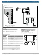
Страница 63: ...LWCO Supply Sensor DHW Sensor Dry contacts Bosch Controls Outdoor Sensor Ź Wire BUS terminal of the Bosch Control to Terminal BB of Greenstar boiler Ź Wire Main power supply 120 v to White molex of Boiler external junction box Ź Wire 120 VAC of Black Molex to Zone Circulator Ź Wire Supply Sensor to terminals in the Heatronic control DHW Thermistor Ź Wire Greenstar Tank thermistor sensor to blue mo...

Страница 64: ...tems may require an additional expansion tank external to the boiler see manual for details Domestic Cold Water Domestic Hot Water Gas Supply Bosch Control Supply Sensor Note See Appendix B for Primary Secondary piping requirements Multi Zone Combi wall boiler Circulators Bosch Control with Zone Relay Bosch Control Zone relay X X Do not connect end switch of relay to boiler Locate the Bosch Contro...

Страница 65: ...ntrol Wiring Line Voltage Ź Wire Main power supply 120 v to White molex of Boiler external junction box Heatronic Internal Wiring B B 4 2 1 A F 9 7 8 LWCO Supply Sensor DHW Sensor Dry contacts Bosch Controls Outdoor Sensor Supply Sensor end switch T T T T T T Zone 3 Zone 1 Zone 2 Zone 3 Zone 1 Zone 2 L N G X X External Boiler Junction box 120 Vac Supply 120 Vac Power Ź Wire 120 Vac power supply to...

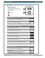
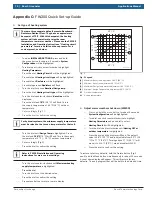
Страница 66: ...l to displaythe first setting 1 Turn the dial to select a setting 2 Press dial to show the current value 3 Press dial to change the value 4 Turn dial to set the required value 5 Press the dial to store the value 6 Press and hold dial until the setting is displayed again 1 Press and hold idal until three dashes appear 2 Release dial The display changes to the standard display and the user interface...

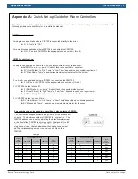
Страница 67: ...ru 8 For CRC200 located in Zone 1 Ź Set DHW to yes pr pump if indirect tank is connected to the system Ź Set Heat System to High Temp or Low Temp depending upon zone requirement Ź Set Max Supply Temp to appropriate maximum temperature for the zone For CRC200 located in zones 2 thru 8 ŹSet Heat System to High Temp or Low Temp depending upon zone requirement ŹSet Max supply Temp to appropriate maxim...

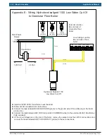
Страница 68: ...d Tees Maximum distance of 4 x pipe diameter center to center based on System header pipe size C System Return Minimum length of 8 x pipe diameter based on System header pipe Boiler Input btu hr Boiler Supply Return pipe diameter System Supply Return Header pipe diameter 57 000 1 1 79 000 1 1 100 000 1 1 25 131 000 1 1 25 151 000 1 1 5 System Header Pipe based on 2 4 ft sec flow velocity system T ...

Страница 69: ...and release Time and Date will be highlighted Push dial again and Time will be highlighted Set time by pushing dial and rotating Once complete push again to lock in time setting Turn dial until Date is highlighted Set date by pushing dial and turning to select Push dial once to lock in date setting 1 2 3 4 5 6 9 12h 15 18 21 24h 3 6 Fig 1 Controller with front flap open Set for constant heating no...

Страница 70: ...sh This is the supply temperature at 5 F 15 C outdoor temperature Set accordingly Fig 2 Press the dial to confirm the setting Refer to FW 200 Installation and Operating Instructions for more custom settings Turn the dial counter clockwise until Maximum heating supply temperature is highlighted Press the dial Turn the dial to set the desired value Press the dial to confirm the setting Press menu bu...

Страница 71: ...ow Water Cut Off ŹInstall a 24VAC 20VA Transformer near the boiler ŹFollow LWCO manufacturer s instructions ŹConnect the lead labeled BOILER GROUND green to the ground wire of the white plug in the boiler junction box ŹConnect the leads labeled 24V HOT red and 24V COMMON white to the external 24VAC transformer field supplied ŹInside the Heatronic Control of the boiler remove jumper from terminal 8...

Страница 72: ...ar the boiler ŹFollow LWCO manufacturer s instructions ŹConnect the lead labeled BOILER GROUND green to the ground wire of the white plug in the boiler junction box ŹConnect the leads labeled 24V HOT red and 24V COMMON white to the external 24VAC transformer field supplied ŹAT the Low Voltage box on the rear of the boiler remove the jumper acros the LWCO connections and connect the leads labeled S...

Страница 73: ...Applications Manual Bosch Greenstar 73 Bosch Thermotechnology Corp Data subject to change ...

Страница 74: ...74 Bosch Greenstar Applications Manual Bosch Thermotechnology Corp Data subject to change ...

Страница 75: ...Applications Manual Bosch Greenstar 75 Bosch Thermotechnology Corp Data subject to change ...

Страница 76: ...United States and Canada Bosch Thermotechnology Corp 50 Wentworth Avenue Londonderry NH 03053 Tel 866 642 3198 Fax 603 965 7581 www boschheatingandcooling com BTC 436001101 C 10 2015 ...

Отзывы: