FPA-1000-V2 Network Cards
Connection | en
11
Bosch Security Systems, Inc.
Installation manual
2017.11 | 2.0 | F.01U.214.374
2.
Run the connector out of the panel enclosure to the next panel to be connected into the
network.
3.
Plug the end of the interconnection cable into the correct port on the networking card for
this panel. Make a note of the port that is used for this connection.
4.
Continue this process from panel to panel until all the panels to be included in the
network are connected and all ports used are noted.
4.3
Verifying network links
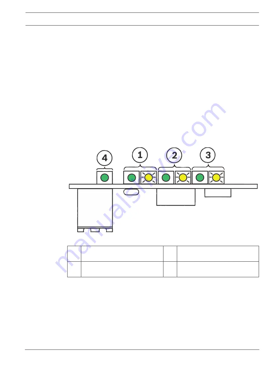
Before proceeding to Panel/network configuration, verify that the network link LEDs are
showing proper connections. Verify the following LED states:
–
The green Power LED for each installed card is ON when the networking card is properly
installed in the panel and the panel has power
–
For each port into which a connector is installed, the green Link LED is ON when a proper
connection is detected between networking cards
–
The yellow Activity LED for any of the three ports flashes when that port is
communicating
For LED identification, see the following figure:
Figure
4.2: Network links - LED status
1 Port 1 LEDS, left LED green = link
right LED yellow = data transmission
2 Port 2 LEDS, left LED green = link
right LED yellow = data transmission
3 Port 3 LEDS, left LED green = link
right LED yellow = data transmission
4 Power LED (green)
Содержание FPE-1000-NE
Страница 1: ...FPA 1000 V2 Network Cards FPE 1000 NE FPE 1000 NF and FPE 1000 NW en Installation manual ...
Страница 2: ......
Страница 17: ......
Страница 18: ......
Страница 19: ......


