background image

- 9 -

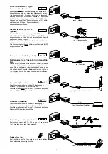
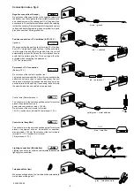
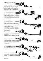
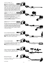
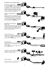
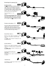
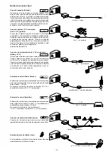
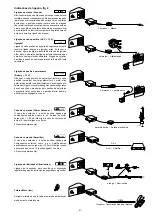
Connection notes, fig. 4

Negative connection (Ground)

Do not connect the negative line to the negative terminal of
the battery. Lay the negative line to a suitable ground, such
as a chassis screw or the chassis itself. Cut the ground line
as necessary. Then strip the insulation and attach a cable lug
(solder if necessary). Remove the paint of the ground contact
surface and treat with graphite grease (important for a good
ground connection).Screw ground line.

Positive conn12 V switched (ACC +12 V)

(Ignition)

+12V

When connecting the positive line to terminal 15 of the fuse
box (+12 V via ignition) behind the fuse, it will be possible to
turn the system on and off via the ignition. Also, the unit will
automatically switch off after one hour of playback time to
avoid that the battery goes flat. This hour logic will not be
activated when connecting the permanent
+12 V line (terminal 30).

Per12 V connection

(B12 V)

per. +12V

Do not connect the vehicle’s positive line !
Lay the red positive wire with a 2.5 mm2 cross section to the
battery (do not route close to vehicle harnesses). Connect
the fuse box to protect the positive line and hook up to the
positive terminal of the battery. If necessary, drill a hole into
the splash wall and use a cable duct as required.

Control wire (Power A)

+12V

The control wire is the switched positive output for external
pieces of equipment such as a
power antenna, maximum load < 150 mA.
Do not connect the control wire to terminal
15 (+12 V switched) or terminal 30 (per12 V).

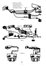
Control wire (Amplifier)

+12V

The control wire is the switched positive output for external
pieces of equipment such as an amplifier or equaliser,
maximum load < 150 mA. Do not connect the control wire to
terminal 15 (+12 V switched) or terminal
30 (per12 V).

Lighting connection (Illumination)           

Lighting connection for vehicles with adjustable dashboard
lighting (plus-controlled).

Telephone Mute (low)

When connecting a phone, the car radio will be automatically
muted when making a call.

Störfreier Massepunkt

5A

PIN 4

5A

+

1

2

3

5A

Kl. 15

Kl.30

12V

5A

Kl.30

12V

15A

per +12V

5A

5A

+12V

5A

P I N 6

red  /  + switched

red  /  permanent

brown  /  ground

yello/green  /  motor antenna

grey  /  telephone mute

blue  /  amplifier

8 622 400 683

Содержание Blaupunkt Heidelberg RCM 126

Страница 1: ...on Löchern darauf achten daß keine Fahrzeugteile Batterie Kabel Sicherungskasten beschädigt werden Der Querschnitt des Pluskabels darf 2 5 mm2 nicht unterschreiten Das Gerät ist mit einer Sicherung 10 A flink abgesichert Das Seitenteil des Autoradiogehäuses wird im Betrieb sehr heiß Achtung Es ist darauf zu achten daß keine Kabel am Gehäuse anliegen Einbauanleitung Fitting instructions Instruction...

Страница 2: ...chnitt von 182 x 53 mm 165 mm Einbauraum und einer Instrumententafeldicke im Bereich der Befestigungslaschen von 1 20 mm siehe Fig 1 HinterdenAutoradioausschnittfassenundprüfen welcheBefestigungs laschen der Halterung umgebogen werden können Hinweis Möglichst alle Befestigunglaschen umbiegen Halterung in den Ausschnitt einsetzen und die Befestigungslaschen mit einem Schraubendreher umbiegen siehe ...

Страница 3: ...2 zur Batte rie verlegen Kabel nicht unmittelbar an Kabelbäumen verle gen Sicherungshalter zur Absicherung des Pluskabels an schließen und am Pluspol der Batterie anklemmen ggf Loch in Spritzwand bohren und entsprechend Kabeldurchführung verwenden Steuerkabel Power Antenna 12V Das Steuerkabel ist der geschaltete Plusausgang für externe Komponenten z B Motorantenne Das Steuerkabel nicht an Klemme 1...

Страница 4: ...nexión com cabo de adaptação e cabo de ligação 3 Fig 6 oder or ou REAR 7 607 886 093 5m ws rt ws rt LR RR LF RF FRONT bl 12V ws rt rt Amplifier Equalizer LR RR RF LF ws 5A 7 607 855 094 Amplifier Equalizer 7 607 863 001 Preamp Out LR RR RF LF 5m 5A 7 607 879 003 7 607 863 001 5 m Fig 5a Fig 4 8 604 390 078 2 1 3 12V per 12V 12V 7 607 884 093 br ge gn or rt rt 5A 15A Kl 15 12V Kl 30 15 7 5 7 5 7 5 ...

Страница 5: ...KD3 Ulmer Straße 30880 Laatzen 1 zu beziehen Spare parts 8 are obtained via central parts dispatch VKD3 Ulmer Straße 30880 Laatzen 1 Pour la fourniture des pièces de rechange 8 s adresser au centre des pièces détachées VKD3 Ulmer Straße 30880 Laatzen 1 5A LR RR RF LF RR RF LF LR 8 604 390 087 7 607 882 090 LF RF LR RR LR RR RF LF Fig 7 Bus NF Fig 4 5 gr rt ge gn br rt or CDC A05 LF RF LR RR Si 3A ...

Страница 6: ...satzteilversand VKD3 Ulmer Straße 30880 Laatzen 1 zu beziehen Spare parts 8 are obtained via central parts dispatch VKD3 Ulmer Straße 30880 Laatzen 1 Pour la fourniture des pièces de rechange 8 s adresser au centre des pièces détachées VKD3 Ulmer Straße 30880 Laatzen 1 LF RF LR RR Si 3A 5A Cinch L Cinch R Bus rt ws Changer Interface rt per 12V ws rt R 30mm br rt CDC F05 R 30mm Fig 4 5 gr rt ge gn ...

Страница 7: ...sicurezza 10 A flink NL Veiligheidsvoorschriften Inbouw en aansluiting Vóór het inbouwen en aansluiten van het toestel dient men de minpol van de accu los te koppelen Let er op dat bij het boren van gaten geen voertuigdelen accu kabels zekeringenkast worden beschadigd De diameter van de pluskabel en de sterkte van de zekering van het toestel zijn afhankelijk van de stroomopname door de apparatuur ...

Страница 8: ... 53 mm 165 installation depth and an instrument panel thickness of approximately 1 to 20 mm in the area of the tab fasteners see Fig 1 Reach behind the car radio compartment and check to see which tab fasteners can be bent for the mounting bracket Note Try to be sure to bend all of the tabs Place the mounting bracket in the compartment and bend over the tabs with the help of a screwdriver see Fig ...

Страница 9: ... 5 mm2 cross section to the battery do not route close to vehicle harnesses Connect the fuse box to protect the positive line and hook up to the positive terminal of the battery If necessary drill a hole into the splash wall and use a cable duct as required Control wire Power Antenna 12V The control wire is the switched positive output for external pieces of equipment such as a power antenna maxim...

Страница 10: ...u de bord de 1 à 20 mm dans la zone des colliers de fixation voir fig 1 Saisir derrière la découpe d autoradio et vérifier lesquels des colliers de fixation peuvent être pliés Note si possible plier tous les colliers de fixation Insérer le support dans la découpe et plier les colliers de fixation à l aide d un tournevis voir fig 1 2 Branchement voir page 4 ou 5 ou 6 Conseils de branchement Fig 4 B...

Страница 11: ...e ne pas poser le câble à proximité immédiate des faisceaux de câbles Connecter le porte fusible pour protéger le câble positif et le connecter au pôle positif de la batterie le cas échéant percer un trou dans le tablier d auvent et utiliser le passe câble Câble de commande Power Antenna 12V Le câble de commande est la sortie positive commutée pour des composants externes p ex antenne de moteur ch...

Страница 12: ... 182 x 53 mm e profondità di 165 mm e con uno spessore di piastrina degli strumenti di 1 20 mm in zona biscottini di fissaggio come da Fig 1 Allacciamento dell autoradio spina ISO in dotazione di veicolo Allacciamento dell autoradio con cavo di adattamento Allacciamento dell autoradio con cavo di adattamento e cavo di allacciamento Inserendolamanodietrol aperturadiautoradiocontrollatequalibiscotti...

Страница 13: ...ettura Posateilcavopositivo rosso consezionemaggiore 2 5mm verso la batteria non posate il cavo direttamente in prossimità deipettinidicavo Allacciateilsupportodeifusibiliaprotezione del cavo positivo e collegate ai morsetti sul polo positivo della batteria eventualmente forate il cruscotto ed usate un corrispondente passacavo Cavo per comandi Power Antenna 12V Il cavo per comandi è l uscita posit...

Страница 14: ...iepte en een dikte van het dashboard bij de bevestigingsstrips van 1 20 mm zie fig 1 Autoradio aansluiting ISO stekker aan de zijde van de auto Autoradio aansluiting met adapterkabel Autoradio aansluiting met adapter en aansluitkabel Voel achter de opening om te controleren welke bevestigingsstrips kunnen worden omgebogen Tip buig indien mogelijk alle bevestigingsstrips om Plaats de houder in de i...

Страница 15: ...uskabel rood met een zware diameter 2 5 mm2 naar de accu leg de kabel niet direct in een kabelbundel Sluit de zekeringhouder ter zekering van de pluskabel aan en klem deze aan de pluspool van de accu boor evt een gat in het spatbord en voer de kabel hierdoor Stuurkabel Power antenna 12V De stuurkabel vormt de geschakelde plusuitgang voor exter ne componenten bv motorantenne maximale belasting 150 ...

Страница 16: ...vid fästtungorna på 1 20 mm se fig 1 Känn efter bakom bilradiourtaget och kontrollera vilka av hållarens Bilradioanslutning Fabriksmonterad ISO kontakt på fordonet Bilradioanslutning med adapterkabel Bilradioanslutning med adapter och anslutningskabel fästtungor som kan böjas in Hänvisning Böj helst in alla fästtungorna Sätt i hållaren i urtaget och böj in fästtungorna med en skuvmejsel se fig 1 2...

Страница 17: ...ea 2 5 mm2 till batteriet Lägg inte kabeln direkt till kabelträd Anslut säkringshållaren för säkring av pluskabeln och kläm fast vid batteriets pluspol borra ev hål i monteringsbrädet och använd motsvarande kabelgenomföring Styrkabel Power Antenna 12V Styrkabeln är den kopplade plusutgången för externa komponenter t ex motorantenn maximal belastning 150 mA Anslut inte styrkabeln till klämma 15 kop...

Страница 18: ...3 mm una profundidad de instalación de 165 mm y un espesor del tablero de instrumentos de 1 20 mm en la zona de las lengüetas de fijación véase fig 1 Verificar cuales de las lengüetas de fijación de la caja pueden ser dobladas Nota Si posible doblar todas las lengüetas para mantener la caja firmemente en posición Instalar la caja en la abertura y doblar las lengüetas utilizando un destornillador v...

Страница 19: ...l de 2 5 mm2 a la batería no colocarlo cerca de mazos Conectar el bloque portafusible para proteger la línea positiva y fijarlo al terminal positivo de la batería Si necesario taladrar una abertura en el panel contra salpicaduras y usar un conducto de cable como requerido Alambre de control Power Antena 12V Elalambredecontrolproporcionalasalidapositivaconectada paracomponentesexternoscomop ej unaa...

Страница 20: ...ão de auto rádio com cabo de adaptação e cabo de ligação Indicação O suporte fornecido com este auto rádio possibilita a montagem em automóveis com uma abertura de auto rádio DIN de 182 x 53 mm 165 mmdeespaçodemontagemeumaespessuradepaineldeinstrumentos de 1 20 mm na área das talas de fixação veja fig 1 Apalpar por detrás da abertura de auto rádio e controlar quais as talas de fixação do suporte p...

Страница 21: ...ia não instalar o cabo directamente à cablagens pré formadas Ligarointerruptordesegurançacomosegurança do cabo positivo e prender ao pólo positivo da bateria se necessário fazer um buraco na parede inferior frontal e utilizar como passagem de cabo Cabo de comando Power Antenna 12V O cabo de comando é a saída positiva ligada para componentes externos como p ex Antena de motor carga máx 150 mA Não l...

Отзывы: