background image

39

5.9

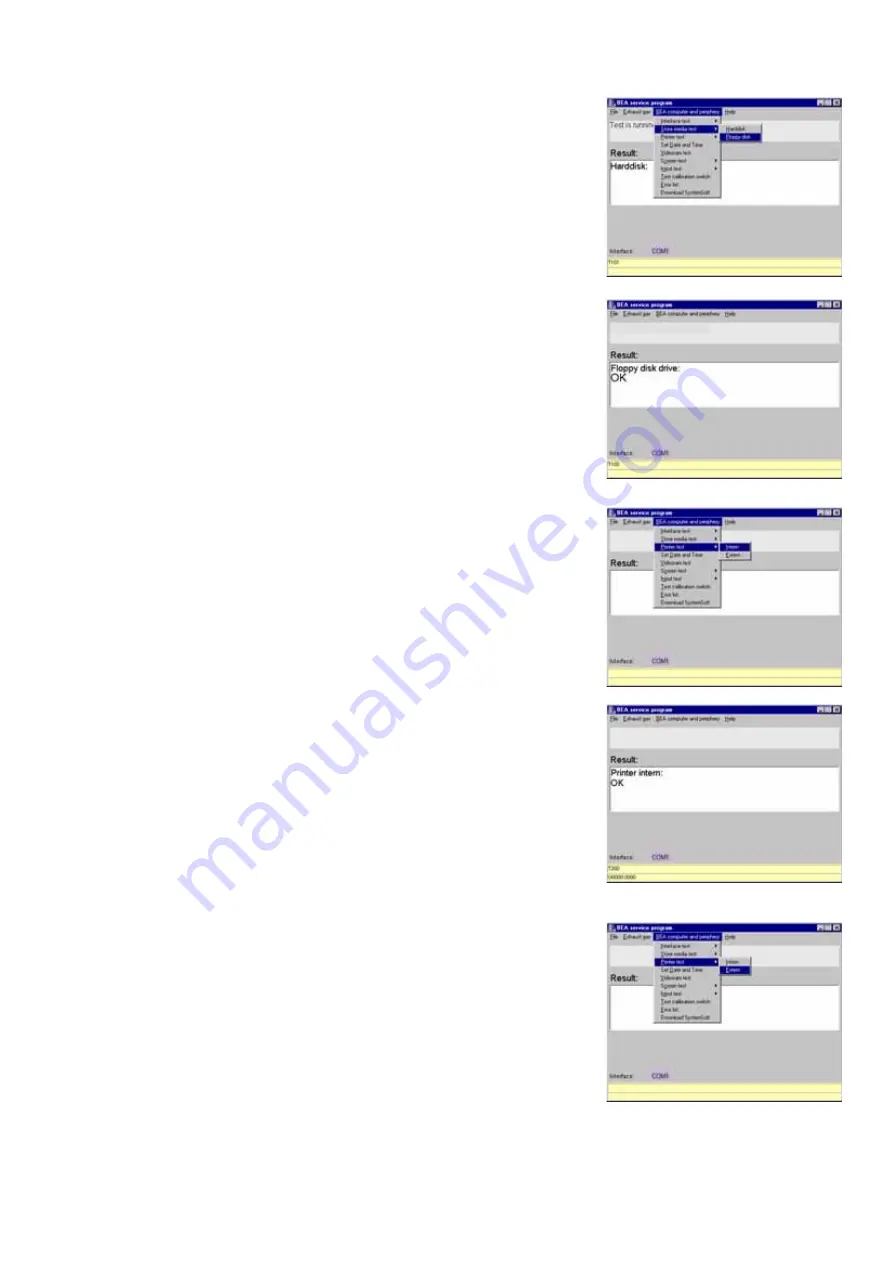
Checking the Floppy disk drive

5.10

Checking the internal printer

5.11

Checking the external printer

Insert an OS9-formatted floppy disk in the
disk drive.
Open the menu 

Store media test

 and

then select 

Floppy disk

.

The Floppy disk drive test is executed
automatically.

If the disk drive test is error-free, the
message 

OK 

appears in the results box.

If the test is unsuccessful, an error messa-
ge is displayed.
For example: B0246:

1300

.

1300

 = No connection to disk drive

Open the 

Printer test 

menu, then select

Intern

.

The printer test is executed automatically.
A printout is produced on the internal
printer bearing the possible font.
The message 

OK 

appears on screen if the

printer test is passed.

Open the 

Printer test

 menu, then select

Extern

.

Содержание BEA 150

Страница 1: ...1 Repair Instructions Bosch Emissions Analysis BEA 150 BEA 250 BEA 350 In conjunction with Service software for PC ...

Страница 2: ...1 Error inquiry 23 4 12 NO Sensor 24 Contents Page 4 12 1 Read NO Sensor 24 4 12 2 Set NO Sensor 24 4 12 3 NO Measurement 25 4 12 4 Mounting a new NO Sensor 25 4 12 5 Readjustment with test gas 28 4 12 6 Read calibration data 30 4 12 7 Calibration interval setting 30 4 12 8 Calibration sequence setting 30 4 13 Checking opacimeter RTM 430 31 5 Checking the PCB and periphery of the BEA control modul...

Страница 3: ...rol module PCB 69 10 3 Block circuit diagram of voltage supply 71 10 4 View of equipment side of control module PCB 72 10 5 Visual inspection of measuring bank of exhaust gas analyzer module 73 10 6 Electrical test of measuring bank of exhaust gas analyzer module 73 10 7 Leak test of measuring bank 73 10 8 Cleaning the lamp reflector 74 10 9 Cleaning the analysis chambers and windows 75 10 10 Repl...

Страница 4: ...d repair work may lead to a risk of accident through electric shock The BEA must not be used to measure explosive gases The exhaust gas analyzer must not be operated in rooms where there is a risk of explosion During work with toxic gases care must be taken to ensure that a concentration which is hazardous to health cannot arise in the workplace Improperly conducted maintenance and repair work may...

Страница 5: ...h z 0 12 V DC stabilizer 2 Testingequipmentandsettingsforthe Servicesoftware 2 1 Testingequipment z 1 laptop or PC z P100 z P140 z Service software for BEA z ESA module system software to test Engine test functions z KTS module system software to test OBD functions i The system software versions for Emissions System Analysis and the KTS module must be installed on your laptop or PC otherwise the S...

Страница 6: ...ed Start the Service program BEAKD Open the File menu Select Set and then Interface Select the appropriate interface and con firm by double clicking the left hand mouse button or by pressing E Enter The interface you have selected is display ed below the results window Start the service program BEAKD Open the File menu Go to Settings and select the Language menu Use the mouse or the o and u keys t...

Страница 7: ...nu and select the RTM menu Open the Swap Languages menu A DOS window is opened with a langua ge selection capability Choose the language by pressing the appropriate number in front of the language on your keyboard After entering the corresponding number the language is automatically changed to ...

Страница 8: ... repeated Here the analyzer module automatically checks whether analysis is currently taking place and if it is delays system calibration until all measured values have fallen to zero 3 1 3 Self test The BEA performs a self test during which it checks all its most important functions Any malfunctions detected result in an error message Section 8 3 1 4 Adjustment HC COandCO2 measuringchannels Durin...

Страница 9: ...ed Section4 5 Writeparameters menu 3 1 10 Parameterization The exhaust gas analyzer module can be parameterized for its specificintendedtasksintheSetparametersmenu Section4 5 Additional possibilities for parameterization are contained in the Adjustment functions menu Section 9 However these like the adjustment functions themselves can only be accessed if a test seal has been broken 3 1 11 Filtrati...

Страница 10: ...menu item Analysismode Sec 4 7 6 Automatic zero calibration takes place Let test gas no 4 sensitivity test or single gases of the appropriate concentration in succession flow through the exhaust gas analyzer via the calibrating gas inlet Note down the displayed values Next use test gases no 5 and no 1 gas mixture for sag test to check linearity and note down the displayed values If the display dev...

Страница 11: ...ions Check unit functions Readadjustmentdata Display setting data important for operation of the exhaust gas analyzer module country specific stipu lations Adjustmentfunctions Settings for the exhaust gas analyzer module Reset Restart the exhaust gas analyzer module When this option is selected the exhaust gas analyzer module is disabled for approx 15 s Errorinquiry Read out the internal fault mem...

Страница 12: ... the exhaust sample probe with the plastic hose or the test bush and confirm by pressing E or clicking OK Follow the instructions on screen The pump is then switched on and off in cycles over a period of approx 3 sec until a certain level of vacuum is reached After this the exhaust gas analyzer module measures the drop in pressure over a period of 15 s The time is counted back wards from 15 s to 0...

Страница 13: ... an HC residue test takes place Next the current measured values for HC CO CO2 O2 lambda COcor and air pressure are displayed The parameters set in the Set parameters mode Section 4 5 are displayed For example Parameters specific to the country of use or required by law are set in this menu ...

Страница 14: ... days 365 days 365 days Gases for recalibration HC CO HC CO HC CO HC CO HC CO No setting HC CO CO2 CO2 CO2 CO2 CO2 CO2 Reaction when recalibration Disable No setting No setting Disable No setting Message No setting due Leak test configuration Days Days NO Days NO Days Days Leak test interval 1 day 1 day NO 1 day NO 1 day 1 day HC residue test YES YES YES YES YES YES YES National regul complied wit...

Страница 15: ...off menu using the o u keys and confirm with E or by double clicking the mouse The OK box is displayed for approx 1 s Lambda calculation is now deactivated Open the COvrai calculation on menu using the o u keys and confirm with E or by double clicking the mouse The OK box is displayed for approx 1 s COcor calculation is now activated Open the COvrai calculation Off menu using the o u keys and conf...

Страница 16: ... double clicking the mouse After confirmation that the O2 sensor is not available the measuring chamber s measuring computer SI BENCH is re started After this it jumps back to the Set parameterssubmenu i Theexhaust gasanalyzeristhenonce more in the warm up phase Further measurement with the Service soft ware is disabled for 60 seconds A message appears on screen i Lambda coefficients must also be ...

Страница 17: ...e OK box is displayed for approx 1 s The HCV and OCV values are stored in the exhaust gas analyzer If you have entered the values incorrectly click No or cancel your entry with E Enter the lambda coefficient values again The software version and checksum of the exhaust gas analyzer module are display ed For example see screenshot You can test various functions of the exhaust gas analyzer module in...

Страница 18: ...f and the OK box is displayed for 1 s SeeSection10 11 Start the menu by double clicking the mouse or with E The pump is switched on and zero calibra tion takes place During this process the O2 measuring channel is recalibrated to 20 9 O2 this same calibration is also performed automatically during each system calibration with zero gas air After zero calibration the pump is swit ched off The exhaus...

Страница 19: ...ith the following concentrations depen ding on requirements HC 400 to 2000 ppm vol C3 H8 entry in propane CO 1 to 10 vol CO CO2 5 to 18 vol CO2 Using the keyboard enter the calibrating gas values for CO as stated on the certi ficate Confirm your entry of these values by clicking OK or by pressing E Using the keyboard enter the calibrating gas values for CO2 as stated on the certifi cate Confirm yo...

Страница 20: ...ation push the calibrating gas hose onto the calibrating gas inlet Start the flow at 1 l min The calibrating gas values are displayed Over a period of 30 seconds the software of the exhaust gas analyzer module com pares the measured values with the entered nominal values If readjustment with test gas has been successful quit the menu by clicking on OK or with E The screen now returns to the Test f...

Страница 21: ...e refore drift and may lead to errors Once you have started this menu zero calibration takes place Push the calibrating gas hose onto the calibrating gas inlet and start the flow at 1 l min Compare the measured values with the calibrating gas values In the event of deviations perform trouble shooting as described in Section 10 Repairs The current air pressure is displayed in hPa Return to the Test...

Страница 22: ...k to the next service date Select Yes by clicking on it or using the tab key Confirm that service has been performed by clicking Yes or by pressing E Confirm the new service date by clicking OK or with E The screen now returns to the Test functions menu Here the parameters set in the Adjust ment functions menu are read out Quit the Read adjustment data menu by clicking OK or with E ...

Страница 23: ... Select Yes by clicking it or with the tab key Confirm that you wish to perform a reset with E or by double clicking the mouse The fault memory is deleted and the exhaust gas analyzer module is restarted i For approx 15 s the exhaust gas analyzer module has no connection to the laptop or PC The following message therefore appears The measuring device reported hardware failure The error code must b...

Страница 24: ...mouse The following menus can be executed z Read NO Sensor z Set NO Sensor z NO Measurement z Mounting an new NO Sensor z Readjustment with test gas z Calibration interval setting z Calibration sequence setting The status of the NO measuring sensor is displayed in this menu In this menu the BEA is informed as to whether or not an NO measuring sensor is installed Confirm your selection of this menu...

Страница 25: ...y pressing Alt B i See Section 10 20 for sensor installation After the NO measuring sensor has been installed it must be calibrated The date of calibration is written in the flashprom enabling the age of the NO measuring sensor to be determined subsequently at any time The same calibrating gas is used for calibrating the NO measuring sensor as for recalibration Before commencing calibration connec...

Страница 26: ...ions depends upon the length of the outlet hoses Following successful calibration the timer for monitoring the set recalibration interval is started Start evaluation by clicking on Yes or selecting this button with the z key and confirming with E Using the keyboard enter the calibrating gas value in ppm NO i If the calibrating gas value is stated on the certificate in mg m3 you must convert this v...

Страница 27: ... sensor is very sluggish An advance flow through the NO measuring sensor is therefore necessary After this flow confirm with E or by clicking OK Assessment is performed The remaining flow time is displayed After calibrating gas has flown through the BEA the measured NO value the corresponding test current and the dateof calibration are displayed To end calibration of the NO measuring sensor confir...

Страница 28: ...n in the illustration below Connect the calibrating gas connection to the test gas inlet 1 Calibrating gas bottle 2 Flow meter rotameter 3 Shutoff valve 4 Tee 5 Test gas inlet Start recalibration with E or by double clicking the mouse Using the keyboard enter the calibrating gas value in ppm NO i If the calibrating gas value is stated on the certificate in mg m3 you must convert this value to ppm ...

Страница 29: ...less ca libration i The NO measuring sensor is very sluggish An advance flow through the NO measuring sensor is therefore necessary After this flow confirm with E or by clicking OK The remaining flow time is displayed Once recalibration has successfully been completed close the calibrating gas bott le End recalibration by pressing E or by clicking OK If you have recalibrated the NO measuring senso...

Страница 30: ... Enter the number of days using the key board Confirm your entry with E or by clicking OK The OK window is displayed for 1 s This menu enables you to define how the BEA should react once the calibration interval has elapsed You can choose between the following options Refuse access when recalibration due Once the calibration interval has elapsed the BEA is disabled and displays a message The BEA i...

Страница 31: ...art the Service program by clicking on Start The Main menu now opens PC Laptop BEA Netzteil RTM 430 COM1 RTM RTM 1 684 465 378 1 684 463 389 459601 6Ha When the Service program starts you can view the software version checksum RTM mode and dip switch settings via the different menu items For example For more details on working with the Service software and repairing the RTM 430 please see EDIS 975...

Страница 32: ...ace test menu and then DTM Remove the 20 way Micro Match plug from X8 of the control module PCB Plug the 20 way shorting plug into X8 of the control module PCB Start the interface test by double clicking the mouse or pressing Enter E If the interface test is error free the message OK appears in the results box If the interface test is unsuccessful an error message is displayed For example B0246 13...

Страница 33: ...plug not jumpered If any error messages other than this one are displayed the control module PCB must be replaced Sec 10 27 Select the Interfaces menu and then AMM Remove the 10 way Micro Match plug from X5 of the control module PCB Plug the 10 way shorting plug into X5 of the control module PCB Start the interface test by double clicking the mouse or pressing Enter E If the interface test is erro...

Страница 34: ...horting plug inserted or pins 3 and 5 of shorting plug not jumpered If any error messages other than this one are displayed the control module PCB must be replaced Sec 10 27 For the functional test of the OBD printed circuit board you will require a 15 pin sliding connector shop made see image below i This menu allows you to test the func tion of the OBD PCB to the outside i e to the vehicle This ...

Страница 35: ...rage are not relevant to the function test of the OBD PCB 5 5 1 Looptest The loop test examines the functional abi lity of the interface in communication with external equipment Perform the loop test by pressing F1 on your keyboard or by double clicking on the loop test button Plug the banana plug rd and GND bk into the and jacks of your DC stabilizer or of your P 100 If the loop test has been con...

Страница 36: ...e that it is securely or faulty fastened replace if necessary Interface on control module PCB faulty Test interface according to repair instructions Sec 4 4 4 replace control module PCB Faulty OBD PCB Perform self diagnosis as per Section 3 1 BsTest Loop TFau 4000 TSchr B and B cables not connected Connect B and B cables Faulty OBD PCB Perform self diagnosis as per Section 3 1 i If any other error...

Страница 37: ...o the OBD CAN connection cable 4 Plug the banana plugs B red and GND black of the KD adapter cable AL 350 into the B and B sockets of the P 100 or a stabilized DC 12V power supply 5 If the loop test has proceeded without errors the following message will be displayed BsTest Loop SDTEST 0000 LBCCTEST 0000 DLCTEST 0000 CANTEST 0000 The critical aspects are the numeric values following xxTEST If the ...

Страница 38: ...sage is displayed For example B0246 1300 1300 No shorting plug inserted or pins 3 and 5 of shorting plug not jumpered If any error messages other than this one are displayed the control module PCB must be replaced Sec 10 27 Open the menu Store meiadia test and then select Hard disk The hard disk test is executed automati cally If the hard disk test is error free the message OK appears in the resul...

Страница 39: ...ly If the disk drive test is error free the message OK appears in the results box If the test is unsuccessful an error messa ge is displayed For example B0246 1300 1300 No connection to disk drive Open the Printer test menu then select Intern The printer test is executed automatically A printout is produced on the internal printer bearing the possible font The message OK appears on screen if the p...

Страница 40: ... open Date Time by double clicking the left mouse button or by pressing Enter E on the keyboard Enter the date and time using the keyboard Confirm your entry by clicking the Set dateandtime button The date and time you have entered now appear in the results box so that you can check them Select the Video RAM test menu then open Video RAM testbydouble clicking the left mouse button or by pressing E...

Страница 41: ...ton or using the Enter E key on the keyboard The geometry image is generated on the BEA s TFT display If the geometry image is in order then the Service software image displays the following reference Geometry image OK In the event of a fault a clear text message is issued Select the Full screen all white menu and open the menu by double clicking on the left hand mouse button or using the Enter E ...

Страница 42: ... In the event of a fault a clear text message is issued In the Input test menu open the Foil keypad menu by clicking it or by pressing Enter E on the keyboard Press membrane keys ESC F1 F2 F3 F4 and F5 one after the other Each membrane key you press is display ed in the results box End the test of the membrane keypad by clicking the End button In the Input test menu open the PC keyboard menu by cl...

Страница 43: ...n by clicking or by pressing Enter E on the keyboard The current switch setting is displayed Select the Error list menu and open by clicking or by pressing Enter E on the keyboard The last 20 stored error messages are displayed This menu is particularly helpful for dea ling with sporadically reported faults This menu is usable for the BEA module BEA 050 and BEA mobile only Downloading of the syste...

Страница 44: ...4 5 24 Versioninformation systemsoftware 5 25 MTMtesting In this menu you can read out the current system software for BEA and the AMM exhaust gas analyzer module i This menu only functions with BEAMobil ...

Страница 45: ...ypres sing F2 or u and open by pressing F5 or E 4 Press F5 or E to open the Conti nuousmeasurementmenu 5 Connect the clamp on pickup lead of the P 140 to the clamp on pickup input of the BEA 6 Connect the temperature lead of the P 140 to the temperature measure ment input of the BEA 7 Switch on the P 140 8 In the No of pulses menu set the number of pulses to 1 using the o or ukeys 9 First of all a...

Страница 46: ...up 6 1 2 Terminaldiagramof temperaturesensor 1 2 3 4 5 1 2 3 4 5 B A A B 463430 R1 R2 1 3 2 1 3 2 Ansicht Lötseite 230036 Resistancetestwithdigitalmultimeter Measured on 3 way amphenol plug pin 1 to pin 2 R 25 C 1005 Ω 5 Ω R 90 C 1530 Ω 12 Ω Viewofsolderside ...

Страница 47: ...F5 or E to open the Gas valuesmenu 5 Connect the clip on trigger sensor to the BEA 6 Clamp the clip on trigger sensor over the loop of your P 140 7 Connect the temperature lead of the P 140 to the temperature measure ment input of the BEA 8 Switch on the P 140 9 In the No of pulses menu set the number of pulses to 1 using the o or ukeys 10 First of all automatic zero calibration takes place 11 Aft...

Страница 48: ...es 80 C 3 C 120 C 3 C 14 Set the speed selector switch of the P 140 to the engine speeds from 600 6000 rpm one after the other Nominalvalues 600 rpm 10 rpm 1500 rpm 10 rpm 4000 rpm 10 rpm 6000 rpm 10 rpm i To perform the V lambda voltage test you will require connection cable 1 684 465 463 1 Press F2 or u to go to the V lambda menu and open it by pressing F5 or E 2 In the No of pulses menu set the...

Страница 49: ...63Ha 6 3 Checking V lambda 6 3 1 Terminaldiagramof V lambdacable 6 4 Checkingtheignitionpointand dwellangle red Solderside black Firstofall automaticzerocalibrationtakes place 3 Connect the clip on trigger sensor to the BEA 4 Clamp the clip on trigger sensor over the loop of your P 100 5 ConnecttheB cableoftheBEAtothe B jack of your P 100 6 Connect the V lambda cable to volta geoutputV C RandrRofy...

Страница 50: ...d justing wheel of the timing light 8 ComparethevalueonyourP100with the value displayed on the BEA Nominalvalue 10 crankshaft 0 5 crankshaft 9 Repeat the test with an ignition point of 60 crankshaft Nominalvalue 60 crankshaft 0 5 crankshaft i Use F3 to change the dwell angle between ms or degrees 1 ConnecttheTerm 1connectioncable green banana plug to the Term 1 jack of your P 100 2 ConnecttheB cab...

Страница 51: ...5ms 0 45ms 7 Repeatthismeasurementwithadwell angle of 50 and an engine speed of 3000 rpm Nominal value 5ms 0 15ms 8 Set your P 100 to a dwell angle of 50 and an engine speed of 1000 rpm 9 Press F3 on the BEA to view the dwell angleindegrees Nominal value 45 0 5 Lötseite 1 6 4 2 5 3 7 8 1 2 3 4 5 6 7 8 ge gn ws br gr rs bl ge gn ws br gr rs bl Cod 1 2 3 4 5 6 7 8 1 3 5 7 2 4 6 8 ZZP Stro Ha grün Be...

Страница 52: ...iable Measuringrange Resolution Calibrationerrorlimit Opacity 0 100 0 1 Country specific Absorption coefficient k 0 9 99 m 1 0 01 m 1 0 3 or 0 45 m 1 in Germany 0 15 m 1 for k 1 m 1 0 15 k1 for k 1 m 1 7 3 EnginemeasurementsystemTDM 7 3 1Temperaturemeasurement Sensor Measuringrange Resolution Tolerance Temperature sensor 20 C 150 C 0 16 C 2 from m v 25 C 1 5 7 3 2RPMmeasurement petrol drivenvehicl...

Страница 53: ... clip on trigger 0 0 60 crankshaft sensor stroboscope to term 1 100 8000 rpm 0 1 crankshaft 0 5 crankshaft 1 dig at or clip on trigger sensor 7 3 6Dwellangle Sensor Measuringrange Resolution Tolerance Terminal 1 0 100 0 1 1 0 360 advance angle 0 1 0 5 0 0 50 0 ms 0 01 ms 0 3 from meas value 1 dig 50 0 99 9 ms 0 1 ms 0 3 from meas value 1 dig 7 3 7Startofdelivery Injectiontiming Sensor Measuringran...

Страница 54: ...s for boot test functions 1100 1099 Malfunction messages on software installation functions 1200 1207 Malfunction messages on print functions 1300 1399 Malfunction messages of hardware test over remote 2000 Malfunction messages of RTM 3000 Malfunction messages of MTM 4000 Malfunction messages of Gas Analysis Module GAM 5000 Malfunction messages of HC11 download 6000 Malfunction messages on OBD pri...

Страница 55: ...ty 12 1 and 12 4 Error in voltage supply Check voltage supply 10 2 and 10 3 Faulty disk drive Check disk drive 5 9 1019 Battery undervoltage Battery faulty or discharged Check battery replace if necessary 10 32 Error in control module PCB Replace control module PCB 10 27 1020 Error in data bus dt5 Error in control module PCB Re boot BEA if error still present 1021 Error in data bus dt6 Re install ...

Страница 56: ...B 10 27 1104 Not enough disk space available Loose interconnecting Check that interconnecting cables cables secure check continuity 12 1 and 12 4 Hard disk error Perform HD test 5 8 Format HD using Service disk 11 1 3 If error still present replace HD 10 23 1105 Error opening file Loose interconnecting Check that interconnecting cables 1106 Errror reading file cables secure check continuity 12 1 a...

Страница 57: ...r still interface present Re install system software 5 23 1302 Error writing serial interface Faulty interface Perform interface test 5 1 5 4 1203 Error reading serial interface Error in control module PCB Replace control module PCB 10 27 1304 Send data different from receive data Error in control module PCB Replace control module PCB 10 27 1305 Error opening disk interface Software error Reboot B...

Страница 58: ...ature sensor sensor Trouble shooting to RTM Repair Instructions 2013 Faulty D A converter Replace D A converter Trouble shooting to RTM Repair Instructions 2014 Negative opacity encountered Zero calibration was performed with gas or calibration filter Perform correct zero calibration if error still present Check solenoid valve and replace if necessary to RTM Repair Instructions 2020 Command not al...

Страница 59: ...r pressure measurement Replace measuring bank 10 10 4034 Insufficient flow Check coarse filters GF1 GF2 GF3 and GF4 replace if necessary Check suction power of pump replace if necessary 10 13 u 10 14 Check flow sensor replace if necessary 10 15 Check hosing as per gas circuit diagram 12 5 Clean condensate separator 10 18 4035 No temperature compensation Replace measuring bank 10 10 4036 Recalibrat...

Страница 60: ...t OK Replace valve 10 19 4090 Unknown error Replace measuring bank 10 10 4091 Parameter error when function called Perform download for exhaust gas analyzer module 9 9 Replace measuring bank 10 10 4099 Exhaust gas analyzer module does Check voltage supply 10 2 and 10 3 not respond Check connection cable 12 1 Replace measuring bank 10 10 8 10 ReferencenumberswhendownloadingDTMfirmware No Designatio...

Страница 61: ...tion Remedy Chapter 6050 Internal module error OBD printed circuit board faulty replace 10 30 CPU printed circuit board faulty replace 10 27 8 11 2 Referencenumbersforerrorsin Statuserror group No Designation Remedy Chapter 6060 Faulty CRC16 checksum OBD printed circuit board faulty replace 10 30 CPU printed circuit board faulty replace 10 27 6061 Level circuit 30 line low Check connecting cable f...

Страница 62: ...9 Invalid data frame KWP2000 6090 Control module busy 6091 Service not supported by control module 6100 Faulty dyn OBD text Run interface test 5 1 5 4 6101 Error when allocating memory OBD printed circuit board faulty replace 10 30 6102 Error when opening OBD text file CPU printed circuit board faulty replace 10 27 6105 OBD module transmits unknown special code 8 12 Referencenumbersincombinationwi...

Страница 63: ...uit plug KS 35 If malfunction no longer present OBD CAN connecting cable should be replaced If malfunction still present OBD CAN LP to be replaced 10 30 0016 0032 0064 OBD CAN connection cable Repeat test using short circuit plug KS 350 0128 or OBD CAN LP defective If malfunction no longer present OBD CAN 0256 connecting cable should be replaced 0512 If malfunction still present OBD CAN LP 8 13 2 ...

Страница 64: ...cable should be replaced If malfunction still present OBD CAN LP to be replaced 10 30 8 13 4 Errormessagesfor CANTEST No Possiblecause Remedy Chapter 0001 OBD CAN connection cable CAN L Repeat test using short circuit plug KS 350 0004 or OBD CAN LP defective If malfunction no longer present OBD CAN connecting cable should be replaced If malfunction still present OBD CAN LP to be replaced 10 30 000...

Страница 65: ...gerät für Abgasuntersuchungen nach Nummer 3 1 und 3 2 der Anlage VIII a zu 47 a StVZO i V m Gerät einsetzbar PTB XX XX XX XX Abgasgerät für Motoren mit Fremdzündung Propane Faktor 0 530 Kalibriergas Qmax xxx L h Qmin xxx L h Test Qsoll xxx L h Qmin xxx L h Meßbereich 0 9999 ppm HC 0 18 vol C02 0 10 vol CO 0 22 vol C2 0 5 9 999 Lamda 02 Sensoren Typ R 17 A Typ A7 11 5 RB Nr 1 687 224 732 RB Nr 1 68...

Страница 66: ...ng the yearly recalibration process Observe legal requirements when making your entry i Enter the gas measuring channels in capital letters The components you have preselected must be contained in the calibrating gas used for recalibration Using the keyboard enter which gas measuring channels are to be recalibrated Confirm your entry with E or by clicking OK The OK box is displayed for 1 s Entry i...

Страница 67: ...played for 1 s Entry is now complete In this menu you can specify whether or not an HC residues test should be perfor med prior to each measurement Select the appropriate setting with the o and u keys and confirm with E or by clicking Next The OK box is displayed for 1 s Entry is now complete This is where you can enable the change of setting for COvrai This setting work is obli gatory as it is a ...

Страница 68: ...nload select Yes with the z key and confirm with E or simply click on Yes with the mouse The directory and name of the download file is displayed to allow you to check and enter new software Using the keyboard enter the directory and name of the download file Confirm your entry with E or by clicking OK As a safeguard you are asked once again whether download should really be per formed To confirm ...

Страница 69: ...e rear of the unit bearing the voltage must be replaced 10 2 AC DCvoltagesupplytocontrolmodulePCB VoltagesupplyAC ConnectorX18 Pin 3 to Pin 1 14 5 V Pin 3 to Pin 2 11 V Pin 3 to Pin 4 11 V Pin 3 to Pin 5 14 5 V Pin 7 to Pin 6 22 V VoltagesupplyforRTM430 ConnectorX3 Pin 4 to Pin 6 14 5 V Pin 4 to Pin 7 14 5 V Pin 4 to Pin 8 14 5 V Pin 5 to Pin 10 14 5 V Pin 5 to Pin 11 14 5 V Pin 5 to Pin 12 14 5 V...

Страница 70: ...Disk drive 1 2 3 4 AMM Hard disk 1 2 3 4 Pressure switch 1 2 O2 sensor 1 2 3 External printer X7 X34 X25 X20 X21 X9 X16 X23 T U2 U3 U4 GND U2L VCC U2 U3 U4 GND U2L VCC 11 13 1 9 10 12 14 16 6 8 2 4 5V 34 5V 12V 40 25 5V 14 5 VAC 11 VAC 0V 11 VAC 14 5 VAC 22VAC 0V RTM X3 15 10 1 2 3 9V 16V 7 11mV 12V 12V NO2 sensor 12V 22 1 2 3 4 5 1KV 8 9V 16V 12V 16 1 2 3 5V PC keyboard X15 RS 232 X11 6 9 DC DC D...

Страница 71: ...P3 LP 223 X26 X24 1 2 3 1 2 3 X25 1 2 3 4 X22 1 2 3 X5 1 2 15 9 Seriell AMM UAMM UP UV UPUMP Lithium Battery 3 0 V FD HD LP DTM LP OBD X6 1 2 15 9 1 2 20 19 X8 X19 1 2 3 X20 1 2 X21 1 2 3 4 12V 12V 5V 9 16V Printer 9 16V 12V UHD 12V 5V UFD 5V TFT Display UTFT B 1KV Keyboard 1 2 3 IR 5V X17 X4 X13 X12 ...

Страница 72: ...ts brightness is not diminished Load valid software in the measuring bank Replace the measuring bank z The LED lights up brightly at first then halves its brightness but then commences this cycle again after a short time The power supply to the measuring bank is not capable of supplying the high making current once the lamp has been switched on Check the power supply ensure that higher making curr...

Страница 73: ...s to the exhaust gas analyzer module 4 Carefully pull the exhaust gas analyzer module out of the unit from behind 5 Remove the fastening screw 1 for the lamp retaining clip 2 6 Remove the retaining clip 2 7 Carefully release the retaining clip 4 of the temperature sensor 5 and take out the temperature sensor 8 Disconnect the interconnecting cable for the lamp from the motherboard of the measuring ...

Страница 74: ...eiver chamber 6 Take care to ensure that the two nuts 5 do not get lost inside the analysis chamber 9 Remove the O rings 7 and windows 8 of the analysis chambers Cleaningtheanalysischambers Immerse a soft bottle brush in liquid cleaning agent which has been diluted as specified and carefully brush the inner aluminium surfaces of the analysis chambers Take care that no liquid if possible gets behin...

Страница 75: ...t gas analyzer module by securing the two fastening screws in the underside of the unit Perform the following adjustment work z Leak test Section 10 7 z Check the measuring accuracy of all three infrared components Section 4 3 z Check cross sensitivity to water vapour Section 10 12 10 11 InstallnewO2 sensor After unpacking the new O2 sensor allow it to be preconditioned to the ambient air for at l...

Страница 76: ...ration of 30 seconds 10 Following correct O2 calibration the new data are displayed 11 End O2 assessment with E or by clicking No If there is a fault during calibration this is displayed in plain text In this case repeat calibration The O2 sensor may need to be replaced again ...

Страница 77: ... flow meter Nominalvalue 3 4 l min 6 Connect the flow meter rotameter to the measurment gas intake of the BEA see diagram 7 Read the flow on the flow meter Nominalvalue 4 7 l min Best Nr 1687 022 768 FD xxx Best Nr Typ Geräte Nr FD U V P W F Hz Made in Germany 088 UEA 100 150 200 250 300 350 mit RTM 400 PTB RTM 430 Geräte Nr RWTÜV A 13 99 Geräte Nr Abgasmeßgerät für Abgasuntersuchungen nach Nummer...

Страница 78: ...n 1 687 222 167 will be installed In order to fasten these in place angle bracket 1 681 332 269 also has to be fitted For mounting details see the Installation instructions 1 689 978 483 1 Start the leakage test Sec 4 2 using the Service software If a leak test can now be performed and it is passed the pressure sensor is deemed to be in order If a leakage test cannot be perfor med a message appear...

Страница 79: ...he exhaust gas analyzer modu le on the rear of the BEA unit 3 Pull the exhaust gas analyzer module approx halfway out of the BEA 4 Remove all hose lines from the water separator 5 Remove the O2 measuring sensor 3 from the rear of the exhaust gas ana lyzer module 6 Remove the four fastening screws 4 for the water separator 7 Take out the water separator 8 Fit the new water separator by pro ceeding ...

Страница 80: ...according to the valid regulations The code number for its disposal is 16 05 02 EAK code Europäischer Abfall Katalog European Waste Catalogue As an alternative to disposal by public services these parts may also be sent to AA W 495 Zentralin standsetzung Central Repairs Dept for disposal Procedure 1 Unscrew the cap 1 of the NO sen sor which is on the back of the unit 2 Unplug the sensor connector ...

Страница 81: ...rinting mechanism under the foil cable 4 Pull the printing mechanism downwards and out 5 Insert the new printing mechanism On installing take care to ensure that the two lugs 4 of the printing mechanism holder are in the recess of the mechanism Take care not to damage the foil cable 2 when screwing in the fixing bolt 3 6 Route the foil cable through the aperture 5 in the plastic panel 7 Plug the f...

Страница 82: ...er supply to the bulb of the TFT display from the control module PCB 5 Unscrew the four fixing bolts 5 of the front panel in the interior of the unit 6 Remove the front panel 6 7 Unscrew the two fastening screws 7 at the top and bottom of the holder panel 8 for the TFT display 8 Remove the four fastening screws 9 from the holder panel 8 of the TFT display 9 Remove the holder panel 8 10 Install the...

Страница 83: ...cing the receiver diode for the remote con trol i In order to remove the receiver diode without problem you must first remove the exhaust gas analyzer module 1 Pull the foil cable 1 of the TFT display out of receptacle X 17 on the control module PCB 2 Pull the foil cable 2 of the membrane keypad out of X13 on the control module PCB 3 Pull the cable of the receiver diode 3 off connector X12 on the ...

Страница 84: ...y remove the PCB from the retaining panel 7 Place the new PCB on the retaining panel and carefully press it onto the panel until the PCB clicks into the holder 5 8 Screw the retaining panel and PCB in place in the unit 9 Push the earthing cable onto the tab on the retaining panel 10 Plug all plug connections back into the control module PCB 11 Perform a function test Sec 5 1 10 28 Replacing the co...

Страница 85: ...etrofit kit and thread the OBD CAN circuit board interface plug 4 through the opening i The opening in the cover plate for the interface plug is offset from the center Take care that the narrow side of the plate faces upwards 5 Pick up the circuit board and cover plate and place the circuit board on the circuit board mounting studs 6 6 Carefully press the circuit board on to the studs until it aud...

Страница 86: ... the AWN printed circuit board 2 Carefully remove the AWN printed circuit board 3 Detach the connecting cable for the AWN printed circuit board to the computer board on the AWN printed circuit board X1 4 Mount the new AWN printed circuit board in the reverse sequence to dismantling it 1 X1 ...

Страница 87: ...ry in place Take care to ensure the correct polarity 3 Check the date and time Sec 5 12 10 33 Replacing the hard disk i The hard drive 1 687 022 809 will no longer be available as of March 2005 as it has been replaced by the Silicon Disc 1 687 370 291 In devices with a release date of 10 2000 or later this hard drive must be replaced with the Siliocon Disc 1 687 370 293 in the course of repair wor...

Страница 88: ...lay program memory Delete program memory Delete configuration memory Floppy check floppy disk drive Language selection Exitprograms BEA Test Vers 1 0 Main menu Harddisk Flash Floppy Language Exit Program Select with F1 UP or F2 DOWN Accept with F5 ENTER Abort with ESC 11 1 Hard disk Procedure 1 Use key F1 or F2 to select the Hard disk menu 2 Start the menu using the F5 key The following menu optio...

Страница 89: ...atting will result in the loss of all stored data Should the media be formated anyway Continue with F5 Enter or abort with ESC 3 Confirm by pressing the F5 key The following reference is displayed for the duration of the formatting process 4 Confirm the inquiry by pressing the F5 key Formatting of the hard disk is started 5 Thefollowingmessageisshownoncetheformattinghasbeen successfullyperformed I...

Страница 90: ...g the F5 key A write test on the disk then follows 6 The following picture is displayed if the write test is passed In the event of a fault the floppy disk has to be replaced see chapter 10 22 7 Confirm by pressing the key F5 Enter 11 4 Language11 4 Language This menu can be used to select the BEA test software language 1 Use F1 or F2 key to select the Language menu 2 Open the menu using the F5 ke...

Страница 91: ...92 12 Overview 12 1 Electrical wiring Siemens analysis chamber 459716 2Ha ...

Страница 92: ...ketten laufwerk 1 2 3 4 AMM Festplatte 1 2 3 4 Druck schalter 1 2 O2 Sensor 1 2 3 Externer Drucker X7 X34 X25 X20 X21 X9 X16 X23 T U2 U3 U4 GND U2L VCC U2 U3 U4 GND U2L VCC 11 13 1 9 10 12 14 16 6 8 2 4 5V 34 5V 12V 40 25 5V 14 5 VAC 11 VAC 0V 11 VAC 14 5 VAC 22VAC 0V RTM X3 15 10 1 2 3 9V 16V 7 11mV 12V 12V NO2 Sensor 12V 22 1 2 3 4 5 1KV 8 9V 16V 12V 16 1 2 3 5V PC Tastatur X15 RS 232 X11 6 9 DC...

Страница 93: ... 22 21 1 2 22 21 1 2 1 2 4 5 1 2 7 8 1 2 5 6 X4 X5 X6 OT Opto ZLP Temp U Lambda X8 3 3 4 5 1 2 4 5 3 X3 X8 1 2 5 6 3 4 1 2 4 5 3 X2 X1 TRZ KL 1 U Batt Diesel 1 2 9 10 1 2 9 10 X22 1 2 3 4 1 2 3 1 2 3 Pumpe Ventil X24 X26 1 2 33 34 1 2 1 2 33 34 1 2 Diskettenlaufwerk 1 2 3 4 1 2 39 40 1 2 39 40 Festplatte 1 2 3 4 Druck schalter 1 2 3 4 5 NO2 Sensor 1 2 O2 Sensor 1 2 3 1 2 3 3 2 1 1 2 24 25 Externer...

Страница 94: ...95 12 4 Hosing Siemens analysis chamber X26 X24 X25 X22 X5 LP 223 X19 459716Ht ...

Страница 95: ... 3 Rückschlagventil WS1 2 Winkelstutzen GP Gaspumpe KA Kondensatabscheider KP Kondensatpumpe DS1 5 Durchgangsstutzen GA1 Gasanalysator CO HC CO2 Messkammer SR Schlauchreduzierung GA2 Gasanalysator O2 Meßwertgeber MV Magnetventil GA3 Gasanalysator NO Meßwertgeber SZB AF1 Aktivkohlefilter TS1 2 T Stutzen PS 1 Drucksensor DD1 2 Dämpfungsdrossel SL1 11 Schlauchleitung Innendurchmesser 5 mm FPM Viton S...

Страница 96: ...97 12 6 Electrical wiring Andros analysis chamber 4597162Ht ...

Страница 97: ...tten laufwerk 1 2 3 4 AMM Festplatte 1 2 3 4 Druck schalter 1 2 O2 Sensor 1 2 3 Externer Drucker X7 X34 X25 X20 X21 X9 X16 X23 T U2 U3 U4 GND U2L VCC U2 U3 U4 GND U2L VCC 11 13 1 9 10 12 14 16 6 8 2 4 5V 34 5V 12V 40 25 14 5 VAC 11 VAC 0V 11 VAC 14 5 VAC 22VAC 0V RTM X3 15 10 1 2 3 9V 16V 7 11mV 12V 12V NO2 Sensor 12V 22 1 2 3 4 5 1KV 8 9V 16V 12V 16 1 2 3 5V PC Tastatur X15 RS 232 X11 6 9 DC DC D...

Страница 98: ...7 22 21 1 2 22 21 1 2 1 2 4 5 1 2 7 8 1 2 5 6 X4 X5 X6 OT Opto ZLP Temp U Lambda X8 3 3 4 5 1 2 4 5 3 X3 X8 1 2 5 6 3 4 1 2 4 5 3 X2 X1 TRZ KL 1 U Batt Diesel 1 2 9 10 1 2 9 10 X22 1 2 3 4 1 2 3 1 2 3 Pumpe Ventil X24 X26 1 2 33 34 1 2 1 2 33 34 1 2 Diskettenlaufwerk 1 2 3 4 1 2 39 40 1 2 39 40 Festplatte 1 2 3 4 Druck schalter 1 2 3 4 5 NO2 Sensor 1 2 O2 Sensor 1 2 3 3 2 1 1 2 24 25 Externer Druc...

Страница 99: ...100 12 9 Hosing Andros analysis chamber 459869_03Ht ...

Страница 100: ...101 12 10 Gas circuit diagram Andros analysis chamber ...

Страница 101: ...BD Netz Einschalter DTM T TFT Display Tastatur IR Empf Interner Drucker Diskettenlaufwerk Festplatte Steuerrechner Abgasmeßmodul O2 NO2 NO Pumpe Magnetventil Druckschalter Messkammer Gas eingang Nullgas eingang Gas ausgang Sys_Uebers BEA ...

Страница 102: ...hap 2 Test equipment AL350 and KS350 added Chap 5 6 Test for 26 pin interface OBD external with CAN protocol added Chap 8 Reference codes 5xxx 6xxx and xxx added For malfunction message 4031 reference to mains voltage test and setting of magnetic core transformer added Chap 10 23 Exchange of OBD printed circuit board added Chap 12 5 Gas travel schedule adapted 180 rotation of measuring cell 30 09 ...

Страница 103: ... 350 0 684 105 3xx EDIS 975 151 WIF 967 1 En 2008 07 24 Printed in Germany Imprimé en Allemagne Robert Bosch GmbH Automotive Aftermarket Test Equipment Postfach 1129 D 73201 Plochingen www bosch de prueftechnik e Mail Bosch Prueftechnik de bosch com ...

Отзывы: