English–10
3 609 929 977 • (04.10) T
Removal
Caution! Accessories can become hot when the
tool is operated for a longer time. Use protective
gloves.
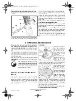
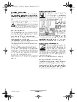
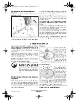
In order to remove the
abrasive, cut-off, or
wire brushing wheel
10
, hold the tool spin-
dle
14
firmly on the
wrench flats with the
open end wrench
17
.
You can unscrew a
stuck outer flange nut
9
from the tool spindle
by using the pin span-
ner wrench
8
, while
you apply a counter-
force on the wrench
flats of the tool spindle
with the open end
wrench.
Subsequently, you can pull the abrasive, cut-off, or
wire brushing wheel, as well as, in the case of angle
grinders with M14 spindle thread, the inner flange
11
,
from the tool spindle. In the case of angle grinders
with 5/8"–11 UNC spindle thread, the inner flange
must be unscrewed from the spindle thread.
Sanding with the Rubber Backing Pad
Installation
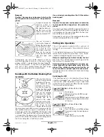
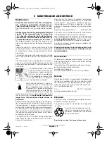
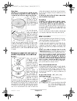
After you have mount-
ed the hand guard
4
together with the aux-
iliary handle
3
(see
Mounting the Protec-
tive Device
), place the
rubber backing pad
5
on the tool spindle
14
.
Then lay the sanding
disc
6
on the rubber
backing pad
5
. Fix the
sanding disc
6
in
place on the rubber
backing pad by plac-
ing the pad nut for flat
discs
7
on the tool
spindle
14
and using
the pin spanner wrench
8
to screw it securely onto the
tool spindle, while you apply a counterforce on the
wrench flats of the tool spindle
14
with the open end
wrench
17
. Take care that the pad nut for flat discs
7
is screwed into the depression of the rubber backing
plate, so that it does not interfere with sanding and so
that the sanding disc is held firmly in place.
Use exclusively sanding discs that fit the rubber
backing pad!
Removal
Caution! Accessories can become hot when the
tool is operated for a longer time. Use protective
gloves.
Use the pin spanner wrench
8
to unscrew the pad nut
for flat discs
7
from the tool spindle
14
, while you apply
a counterforce on the wrench flats
15
of the tool spin-
dle with the open end wrench
17
.
Subsequently, you can pull the sanding disc
6
and the
rubber backing pad
5
from the spindle.
Putting into Operation
The air tool operates optimally with a pressure of
6.3 bar (91 psi) measured at the air inlet with the tool
running.
If, at a higher nominal pressure, the installed accessory
rotates more rapidly than permitted, it may be de-
stroyed and fragmenting parts may injure you.
Remove adjusting keys before turning the tool
on.
A key that is left attached to a rotating part of the
tool may result in personal injury.
After inspecting and installing an accessory, po-
sition yourself and bystanders away from the
plane of the rotating accessory and run the air
tool at maximum no-load speed for one minute.
Damaged accessories will normally break apart during
this test time.
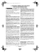
Switching On/Off
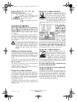
If the tool does not run – for example, after not being
used for a prolonged time – disconnect the air supply
and turn the motor repeatedly using an open-end
wrench
17
on the wrench flats
15
of the tool spindle.
This eliminates adhesion forces.
Type 0 607 352 109/... 112/... 117/... 119
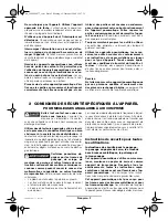
Locking switch
Switching on:
Slide the on/off switch
18
forward.
Switching off:
Slide the on/off switch
18
backward
to release the locking and to switch
off the tool.
Type 0 607 352 113/... 114/... 118/... 120
Deadman switch
Switching on:
Press the on/off switch
18
and keep
it pressed during the working oper-
ation.
Switching off:
Release the on/off switch
18
.
17
10
14
8
9
17
5
14
6
7
8
18
18
bu_3609929977_t.fm Seite 10 Montag, 11. Oktober 2004 12:17 12


