background image

Boomerang


Boomerang  GT


FlyCamOne Carrier

FlyCamOne Carrier

FlyCamOne Carrier

FlyCamOne Carrier


Manual


www.Air-Ace.net


Content ARF 


- Fuselage with 2 Servos  
  and ESC 
- Foam noose 
- Main wings L+R with 2  
  Servos each 
- Elevator unit 
- Rudder 
- Carbon Shaft 
- wooden plate  
- Motor with arm 
- Propeller 
- 4 Screws for the wing  
 (35x30mm) 
- 4 Washer screws for  
  wooden plate(8x2mm) 
- 4 Screws for the motor   
  unit (10x3mm) 
- 2 Washer screws for the  
  linkage of the tail   
  unit(50x2mm) 
- 2 Screws for the rudder  
  unit (20x2mm) 


Contenu du kit 
ARF 

- Fuselage avec 2 Servo et 
ESC 
- Nez en mousse 
- Deux ailes D+G avec 2 
servo par ailes 
- Profondeur 
- Dérive 
- Mât carbone  
- Renfort en bois  
- Moteur avec support  
- Hélice 
- 4 Vis pour les ailes 
(35x30mm) 
- 4 Vis à rondelle pour le 
renfort en bois 
(8mmx2mm) 
- 4 Vis pour le moteur 
(10x3mm) 
- 2 Vis à pour la profondeur 
(50x2mm) 
- 2 Vis pour la dérive 
(20x2mm) 
 

Incluido en el kit 
ARF 

- Fuselaje con 2 Servos y 
ESC 
- Dos alas D+I con 2 servo 
en cada 
- Profundidad 
- Timón 
- Junco carbón  
- Chapa de madera  
- Motor con soporte  
- Hélice 
- 4 Tornillos para las alas 
(35x30mm) 
- 4 Tornillos para la chapa 
de madera (8x2mm) 
- 4 Tornillos para el motor 
(10x3mm) 
- 2 Tornillos para la 
profundidad (50x2mm) 
- 2 Tornillos para el timón 
(20x2mm) 


Содержание FlyCamOne Carrier

Страница 1: ...ontenu du kit ARF Fuselage avec 2 Servo et ESC Nez en mousse Deux ailes D G avec 2 servo par ailes Profondeur Dérive Mât carbone Renfort en bois Moteur avec support Hélice 4 Vis pour les ailes 35x30mm 4 Vis à rondelle pour le renfort en bois 8mmx2mm 4 Vis pour le moteur 10x3mm 2 Vis à pour la profondeur 50x2mm 2 Vis pour la dérive 20x2mm Incluido en el kit ARF Fuselaje con 2 Servos y ESC Dos alas ...

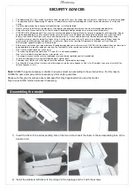
Страница 2: ... motor speed the model is not controllable Before every start check your model above all if being damaged because of former crash NEVER start the model with one of those parts damaged battery propeller engine or steering The functionality of the remote control has to be checked before every start Don t run the model in brine or saline areas The use during temperatures between 5 C and 35 C is not r...

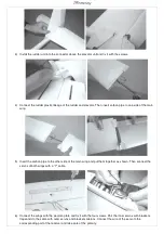
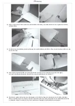
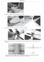
Страница 3: ... Insert the carbon pipe to the other side of the main wing and put them together as shown Then connect the servos of both wings with a Y cable 6 Connect the wings with the wooden plate and fix it with the four screws Pair the inner servos with brackets flaps and do the same with outer servos and brackets ailerons Connect the wire of the servo to the corresponding port of the receiver and take care...

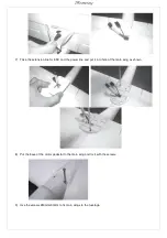
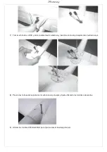
Страница 4: ... line for ESC and the power line and put it into hole of the main wing as shown 8 Put the base of the motor pedestal to the main wing and fix it with the screws 9 Use the screws 350mmx30mm to fix main wings to the fuselage ...

Страница 5: ...opeller to the axe of the motor and keep in my mind that plane must push when flying do not fix it reverse sided 13 Before your first fly you must adjust the center of gravity CG of the plane with the battery inside As on the right picture you will notice two stickers on the plane s fuselage that will let you identify where it is located ...

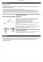
Страница 6: ...n wind goes up to 4 Beaufort Make sure your frequency is not in use by anybody else around you Select a wide area 300x300m min without any obstacles Concentrate onto the model during the whole flight Keep in mind higher grass can protect the model when you ll have a hard touch down Model must be launched against the wind to start climbing in the air Move the stick for acceleration to the back befo...

Страница 7: ...apport aux différentes sortes d obstacle bâtiment public Pour plus de sécurité nous vous conseillons de toujours vous situer derrière le modèle Sans le fonctionnement du moteur le modèle n est pas contrôlable Il est indispensable de vérifier le bon aspect du modèle ainsi que la bonne fixation de toutes les pièces avant chaque vol NE JAMAIS tenter de voler si vous constatez que l un de ces éléments...

Страница 8: ...et effet sur la partie arrière du fuselage et fixer à l aide des vis fournies 20mmx2mm 4 Connecter à présent les chapes plastiques de la profondeur et de la dérive A présent insérer le mât carbone dans l une des deux ailes 5 Insérer par la suite le mât carbone à l intérieur de la seconde aile afin de les réunir comme illustré sur l image Connecter par la suite les servo de chaque aile avec un cord...

Страница 9: ...orrespondantes et faites de même avec les servo externes Enfin connecter les servo au récepteur en veillant à bien respecter la polarité 7 Munissez vous du fil de l ESC et de celui de l alimentation et insérez les dans l aile principale comme illustré 8 Positionner la base du support moteur sur l aile principale et fixer à l aide des vis prévues à cet effet 9 Utiliser les vis 350mmx30mm pour fixer...

Страница 10: ...t effet 12 Enfin installer l hélice sur son axe en vous assurant que celle ci est correctement positionnée Ne pas monter à l envers 13 Avant de voler il est indispensable d ajuster le centre de gravité de votre modèle Celui ci est indiqué sur votre modèle par les deux sticker présents sur le fuselage comme illustré sur la photo ci dessus ...

Страница 11: ...lons de débuter avec un accompagnateur Voler uniquement quand le temps le permet Il sera plus facile de faire voler votre modèle lorsqu il n y a pas de vent Afin de réduire les accidents nous vous conseillons d arrêter de voler si le vent est supérieur à 4 Beaufort Assurez vous que la fréquence utilisée est libre Placez vous dans une zone dégagée 300x300m min sans aucun obstacle Restez concentré s...

Страница 12: ... los obstáculos potenciales edificios publico Para más seguridad le aconsejamos de ubicarse siempre detrás de su modelo Sin utilizar el motor el modelo no puede ser controlado Tiene que verificar el buen aspecto de su material antes de cada vuelo Verificar que todas la piezas han sido bien fijadas NUNCA tiene que volar su modelo en el caso de que una parte de su modelo ha sido rota No utilizar su ...

Страница 13: ... junco carbón en la otra ala afín de reunirlas como ilustrado aquí sobre la imagen Una vez esta etapa efectuada conectar los servo de cada ala con el cordón Y 6 Reforzar la rigidez de las dos alas principales al atornillar la chapa de manera con los tornillos indicados Ahora conectar los servo internos que se encuentran sobre las alas principales con el adecuando canal de su receptor Hacer lo mism...

Страница 14: ...n eléctrica y inserirlos en la ala principal como ilustrado aquí 8 Posicionar la base del soporte motor sobre la ala principal y fijarla utilizando los tornillos adecuados 9 Utilizar los tornillos 350mmx30mm para fijar las alas al fuselaje principal ...

Страница 15: ...os adecuados 12 Por fin instalar la hélice sobre su eje asegurándolo que está bien posicionada Verificar la dirección de la rotación Antes de volar tiene que verificar el centro de gravedad de su modelo Como puede destacar sobre la imagen de izquierda hay marcas rotundas sobre ambas parte de fuselaje Assembling the model ...

Страница 16: ...lismo Volar solo cuando el tiempo lo permite Es más fácil utilizar su modelo cuando no hay viento Afín de reducir el riesgo de accidentes le aconsejamos de parar volar cuando el viento alcanza los 4 grados Beaufort Ubicarse en una zona libre de al menos 300x300m min sin ningún obstáculo Conservar toda su concentración sobre su modelo durante todo Una carretera aislada del tráfico puede también ser...

Страница 17: ...o not mix different types of batteries or old and new batteries When changing batteries replace ALL of the old batteries with new ones Make sure the batteries are installed with the correct polarity as shown in the battery compartment Do not disassemble your transmitter batteries Never allow them to become hot or to burn To avoid short circuits avoid getting them wet If liquid from inside the batt...

Отзывы: