


User’s Manual
57
5.3.11.
R
ED
B
RAKING LIGHT STAYS ON ALL THE TIME
•
Make sure the Bus Discharge input is not activated. This causes the
braking module to go full on. Extended operation with this input can
cause load bank overheating and improper operation.
•
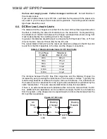
System voltage is too high or high harmonic content is present. Check
main system rectifier input AC voltage. Refer to the DC Bus Trigger Level
found in Table 2-3. The undistorted main system rectifier AC input
voltage should always be less than
.
•
Note: If the measured DC bus (in standby) is greater than the
1.414
*
RMS
Voltage
Line
then harmonic distortion may exist. Consult the project engineer for the
appropriate corrective action.
•
Setpoint too low. The DC Bus Setpoint pot on the main control board
may have been tampered with. If this is a possibility, then the module
needs to be sent in for recalibration.
•
Wrong braking module installed. Check the module chassis sticker for
the part number. Refer to Section 2.2 of this manual and verify the sticker
information represents the correct part number for your application and
voltage levels. Remove and replace as required.
•
Main control board has gone bad and the module needs to be sent in for
repair.
5.3.12.
M
ASTER
U
NIT APPEARS TO FUNCTION PROPERLY
,
BUT
S
LAVE
U
NITS DO NOT SEEM TO FOLLOW THE
M
ASTER
Slave(s) may have missing or insufficient control voltage. Refer to Section
5.3.1 and correct as required.
Check the signal wiring between modules. The terminals should be daisy
chained as described in Section 4.2.3.1.
Make sure that only one module is selected as Master on a network. More
than one master can cause improper triggering and system damage.
5.3.13.
A
TTACHED
D
RIVE
W
ILL
N
OT
P
RECHARGE
Verify the polarity of the connection to the DC filter capacitors of the drive. If
this connection is reversed, the commutation diode effectively shorts the DC
bus and will not allow the drive to go through precharge.
5.4.
T
ECHNICAL
H
ELP
–
BEFORE YOU CALL
If possible, please have the following information when calling for technical help:
•
Serial number of unit
•
Name of original equipment supplier
•
Brief description of the application
•
Drive and motor HP or kW
•
The line to line voltage on all 3 phases
•
The DC Bus voltage
•
KVA rating of power source
•
Source configuration Wye/Delta and grounding
1.414
/
DC
Level
Trigger
Bus
Содержание M3452
Страница 14: ...M3452 vR7 EIP PDP 14 This page intentionally left blank ...
Страница 19: ...User s Manual 19 Figure 3 2 Customer Connections in K9 Chassis CUSTOMER I 0 CONNECTION ...
Страница 21: ...User s Manual 21 Figure 3 2 Customer Connections in M14 Chassis CUSTOMER I O CONNECTION ...
Страница 24: ...M3452 vR7 EIP PDP 24 Figure 3 6 I O Hookup with R7 EIP PDP Communication ...
Страница 26: ...M3452 vR7 EIP PDP 26 Figure 3 8 24VDC Power Connection ...
Страница 58: ...M3452 vR7 EIP PDP 58 This page intentionally left blank ...
Страница 66: ...M3452 vR7 EIP PDP 66 Figure 6 3 M3452 K9 Chassis Dimensional Outline Drawing ...
Страница 68: ...M3452 vR7 EIP PDP 68 Figure 6 5 M3452 M14 Chassis Dimensional Outline Drawing ...
Страница 75: ...User s Manual 75 NOTES ...
Страница 76: ...M3452 vR7 EIP PDP 76 This page intentionally left blank ...
Страница 77: ......
Страница 78: ......
Страница 79: ......