SW 053-A.01 MANUAL Rev.00 Last update 02.12.2020
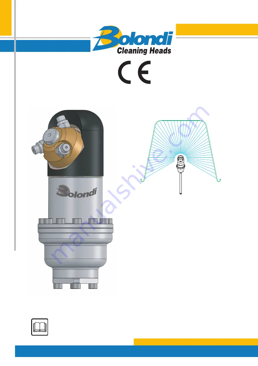
SERVICE MANUAL
SW 053-A.01
SERIAL N°:XXXXXXXX
WARNING:
THIS MANUAL IS AN INTEGRAL PART OF THE MACHINE AND MUST BE READ AND
KEPT FOR REFERENCE
Translation of the original instructions
Страница 1: ...v 00 Last update 02 12 2020 SERVICE MANUAL SERVICE MANUAL SW 053 A 01 SERIAL N XXXXXXXX WARNING THIS MANUAL IS AN INTEGRAL PART OF THE MACHINE AND MUST BE READ AND KEPT FOR REFERENCE Translation of the original instructions ...
Страница 2: ...TY 5 1 INTRODUCTION 6 2 RECEIVING AND UNPACKING 7 3 CONDITIONS AND LIMITS OF USE 8 4 GENERAL SAFETY INSTRUCTIONS 9 5 TECHNICAL SPECIFICATIONS 10 6 DIAGRAM OF THE ASSEMBLY 12 7 INSTALLATION AND COMMISSIONING WARNINGS 13 8 CHOICE OF DIFFUSER ACCORDING TO FLOW RATE 14 9 MAINTENANCE 15 10 SPARE PARTS 26 TABLE B TORQUE WRENCH SETTINGS 27 EXPLODED VIEW 28 ...
Страница 3: ...d equipment classified in art 4 cat 3 It also complies with the following harmonised European standards ISO TR 14121 2 2013 Guidance document for risk assessment UNI EN ISO 12100 2010 Safety of machinery General principles for design The undersigned also declares that the incomplete machine cannot be started up until the machine on which it will be incorporated and of which it will become part has...
Страница 4: ...s measured at the workstation at 1 m from the machine surface and 1 6 m off the ground in normal machine operating conditions Sound intensity measurements gave readings below 70 dB A Measurement of vibrations was not made as these were considered clearly below risk levels The intensity of the sound produced by machine operation is normally below sound intensity caused by the impact of washing wate...
Страница 5: ...warranty shall be decided indisputably by the manufacturer 5 The warranty excludes labour and transport costs which are always the responsibility of the purchaser 6 All spare parts replaced under warranty must be returned to the manufacturer carriage paid within a maximum of 20 days 7 The warranty on the finished product or its components shall be void if the product is tampered with modified or h...
Страница 6: ... accompany the symbol N B For accident prevention purposes the equipment must be fitted with suitable devices to prevent automatic re starting when the equipment is powered after a shut down The head must not be used without these devices The Manufacturer declines all responsibility in the case of improper use of the equipment N B Please consult the chapter EXPLODED VIEW for all the numbers and re...
Страница 7: ... in his country as regards to disposing of consumables and materials resul ting from demolition Please remember that by waste is meant any substance or object under obligation of dispo sal According to their origin and pursuant to the above mentioned Decree waste products are classified as urban or special waste and depending on their dangerous characteristics as hazardous or non hazardous waste W...
Страница 8: ...uipment if it is not in perfect condition 3 3 Intended use the head was designed exclusively for washing closed contai ners 3 4 Improper use any other use that does not comply with the safety standards indicated in this manual is to be considered improper 3 5 Declaration of the manufacturer if the head is installed as a component on machines or systems it is forbidden to use it before the latter h...
Страница 9: ...he supply motor pump is fitted with a relief valve and its setting is compati ble with the head 4 8 Make sure the quantity and diameter of the nozzles are suitable for the characteristics of the plant pump pressure and flow 4 9 The high pressure hose must be perfectly intact to avoid the risk of bursting If the high pressure hose is damaged it must be replaced immediately 4 10 Do not inspect the c...
Страница 10: ...ATURE 90 C WATER INLET 1 2 FILTER 700 MICRON NUMBER OF NOZZLES 2 3 4 NOZZLES 1 8 NPT O RING NBR EPDM VITON SEALS PTFE CARBON FIBRE MATERIAL AISI 316 ALUMINUM BRASS MIN CENTER LINE THROUGH HOLE Ø114 MM MIN MANUAL THROUGH HOLE Ø90 MM DIFFUSER SEE CHART A CONICAL GEARS FIXED Z 22 ROTATING Z 23 MODULE 2 FULL CYCLE 23 ROTATIONS FULL CYCLE TIME 15 AT 90 RPM WEIGHT KG 2 700 5 ...
Страница 11: ...2 204 WATER INLET 1 2 G VERSIONE FOGLIO NOTE SCALA SW053 AA 1 1 A3 CODICE 01 DATA 01 02 03 04 05 MONTECCHIO E RE ITALY CONTR CLEANING HEADS DATA DISEGN 09 03 20 CR VERSIONE DM VERSIONE FOGLIO DATA 06 07 08 09 10 DESCRIZIONE XXXX 09 03 20 SW 053 A 01 APPLICATION DRAWING ...
Страница 12: ...A 01 MANUAL Rev 00 Last update 02 12 2020 DIAGRAM OF THE ASSEMBLY 1 Rotating head 2 Nozzle 3 Nozzle holder 4 Identification plate 5 Main body 6 Water inlet 06 SW053 00 EN 6 5 4 3 2 3 way version 4 way version 1 6 ...
Страница 13: ...of any waste or impurities Any breakage or problem due to waste and or impurities is not covered by the warranty It is advisable to install a 60 micron filter between the head and the pump assembly Install a safety valve on the head delivery set at the maximum pressure indicated on the rotating head or in the Technical Data Chapter in this Manual N B Do not turn the nozzle holder by hand N B The h...
Страница 14: ...consignment the head is built as requested in the order placed If the flow rate is varied for best use replace the diffuser pos 4 From table A choose the most suitable diffuser pos 4 for the new parameters It is understood that in the event of variations the nozzles pos 30 must also be replaced Before you make any changes you are recommended to contact the manufacturer Follow the procedure given i...
Страница 15: ...rque values of components tightened with a torque wrench Lubricant recommended for maintenance PETRONAS TUTELA ZETA 2 grease 9 1 CLEANING THE INLET FILTER POS 3 Disassembly 9 1 1 Use a 5 mm allen wrench to loosen and remove the screws pos 2 disassemble the filter holder flange pos 1 and remove the cartridge pos 3 Fig 9 00 9 1 2 Clean the cartridge pos 3 thoroughly make sure there is no breakage an...
Страница 16: ... torque wrench 9 2 REPLACING THE DIFFUSOR POS 4 Disassembly 9 2 1 Remove the inlet filter as explained in section 9 1 1 9 2 2 Use a 5 mm allen wrench to loosen the twelve screws pos 2 from the body pos 23 see fig 9 02 9 2 3 Remove the top casing pos 24 and push out the diffusor pos 4 Fig 9 03 then re place it after having selected the desired diffusor as per table A chapter 8 MAINTENANCE Fig 9 02 ...
Страница 17: ...ly see fig 9 04 9 2 6 Position the top casing and secure it with the twelve screws pos 2 Use a torque wrench to tighten 9 2 7 Re fit the inlet filter as specified in section 9 1 3 at 9 1 5 9 3 REPLACING SEALS POS 29 IN THE NOZZLE HOLDER HUB POS 17 Disassembly 9 3 1 Use a 17 mm fixed jaw spanner to unscrew the pin pos 20 Fig 9 05 MAINTENANCE 20 Fig 9 05 9 Fig 9 04 Pos 4 Kit Pos 5 Pos 6 Kit Pos 5 Po...
Страница 18: ...CE 9 3 2 Slide out the pin pos 20 from the nozzle holder crown and remove the washers pos 15 19 Fig 9 06 9 3 3 Use the dedicated tool to remove the seals and the O ring pos 29 from their seats on the nozzle holder unit Fig 9 07 20 19 17 15 Fig 9 06 Fig 9 07 29 9 ...
Страница 19: ...ntroduction of the ring follow the indications shown in fig 9 08 9 3 5 Make sure all components are fitted correctly in their seats and lubricate with grea se 9 3 6 Fit the washer pos 19 on the pin pos 20 first then insert the pin in the nozzle hol der crown to make it easier to fit the threaded part through the seals turn as if screwing then fit the second washer pos 15 Fig 9 09 OK NO NO Fig 9 08...
Страница 20: ... on the thread of the pin pos 20 screw the com plete unit onto the casing pos 16 Fig 9 10 and tighten using a 17 mm fixed jaw spanner checking for correct coupling of the bevel gears pos 13 and pos 17 see exploded view diagram Use a torque wrench to tighten MAINTENANCE Fig 9 10 Loctite 572 9 ...
Страница 21: ...PINION POS 13 Disassembly 9 4 1 Using a no 17 spanner unscrew the pin pos 20 as explained in paragraph 9 3 1 and remove the complete unit 9 4 2 Disassemble the top casing pos 24 from paragraph 9 2 1 to paragraph 9 2 3 9 4 3 Remove all components from the head as shown in fig 9 11 and fig 9 12 Fig 9 11 Fig 9 12 9 ...
Страница 22: ...2020 9 4 4 Insert the special key code BZ0031 on the central shaft pos 9 and use a 17 mm fixed jaw to unscrew the above part Fig 9 13 9 4 5 Remove the casing pos 16 and the washer pos 15 Fig 9 14 MAINTENANCE 1 7 Fig 9 13 Fig 9 14 9 15 16 23 ZB0031 9 ...
Страница 23: ...ve the seals and the O rings pos 29 from their seats Fig 9 16 9 Fig 9 15 Fig 9 16 12 12 11 Assembly 9 4 8 Replace the O ring in its seat and then the sealing ring pos 29 making them adhere perfectly to the O ring using a blunt tool To make it easier to insert the ring follow the instructions in Fig 9 08 9 4 9 Make sure everything is assembled correctly in place in its housing and properly greased ...
Страница 24: ... of the balls facing down Fig 9 17 9 4 11 Insert the output shaft pos 9 into the bottom casing pos 23 to make it easier to fit the threaded section through the seals turn the shaft as if it were being screwed in 9 4 12 Insert the washer pos 15 in the shaft pos 9 and screw the casing pos 16 on the same put a few drops of Loctite 222 on the thread tighten with the dedicated key code ZB0031 and torqu...
Страница 25: ...10 the planetary gears hol der pos 7 the three planetary gears pos 8 the flange pos 21 check the O ring pos 27 and replace if necessary fig 9 19 9 20 9 4 14 Position the washer pos 6 and check if the assembly is correct making sure there isno friction between the part pos 6 and the gears pos 8 see fig 9 21 9 4 15 Install the complete impeller unit and finish the installation as described from pa r...
Страница 26: ...d be requested to following address Bolondi Via A Volta 4 42027 MONTECCHIO RE ITALY Tel 39 0522 864434 Fax 39 0522 865780 e mail bolondi bolondi com always indicate the model and serial number of the head see identification plate the code and description of the part ordered see table the quantity required the preferred means of shipment 11 000 00 EN ...
Страница 27: ...27 SW 053 A 01 MANUAL Rev 00 Last update 02 12 2020 27 TABLE B TORQUE WRENCH SETTINGS TORQUE WRENCH SETTINGS Structural screws Pitch Nm M6 11 All M12X1 00 30 All Nozzles Pitch Nm 1 8 npt 5 ...
Страница 28: ...28 SW 053 A 01 MANUAL Rev 00 Last update 02 12 2020 EXPLODED VIEW 4 4 4 4 326 4 4 4 326 4 4 326 2 5 1 6 7 4 326 326 326 326 4 4 6 ...
Страница 29: ...Via A Volta 4 Tel 0522 864434 Fax 865780 42027 MONTECCHIO E Reggio E Italy E mail bolondi bolondi com www bolondi com SW 053 A 01 MANUAL Rev 00 Last update 02 12 2020 ...